

Air foaming pump trigger sprayer
- Summary
- Abstract
- Description
- Claims
- Application Information
AI Technical Summary
Benefits of technology
Problems solved by technology
Method used
Image

Examples
Embodiment Construction
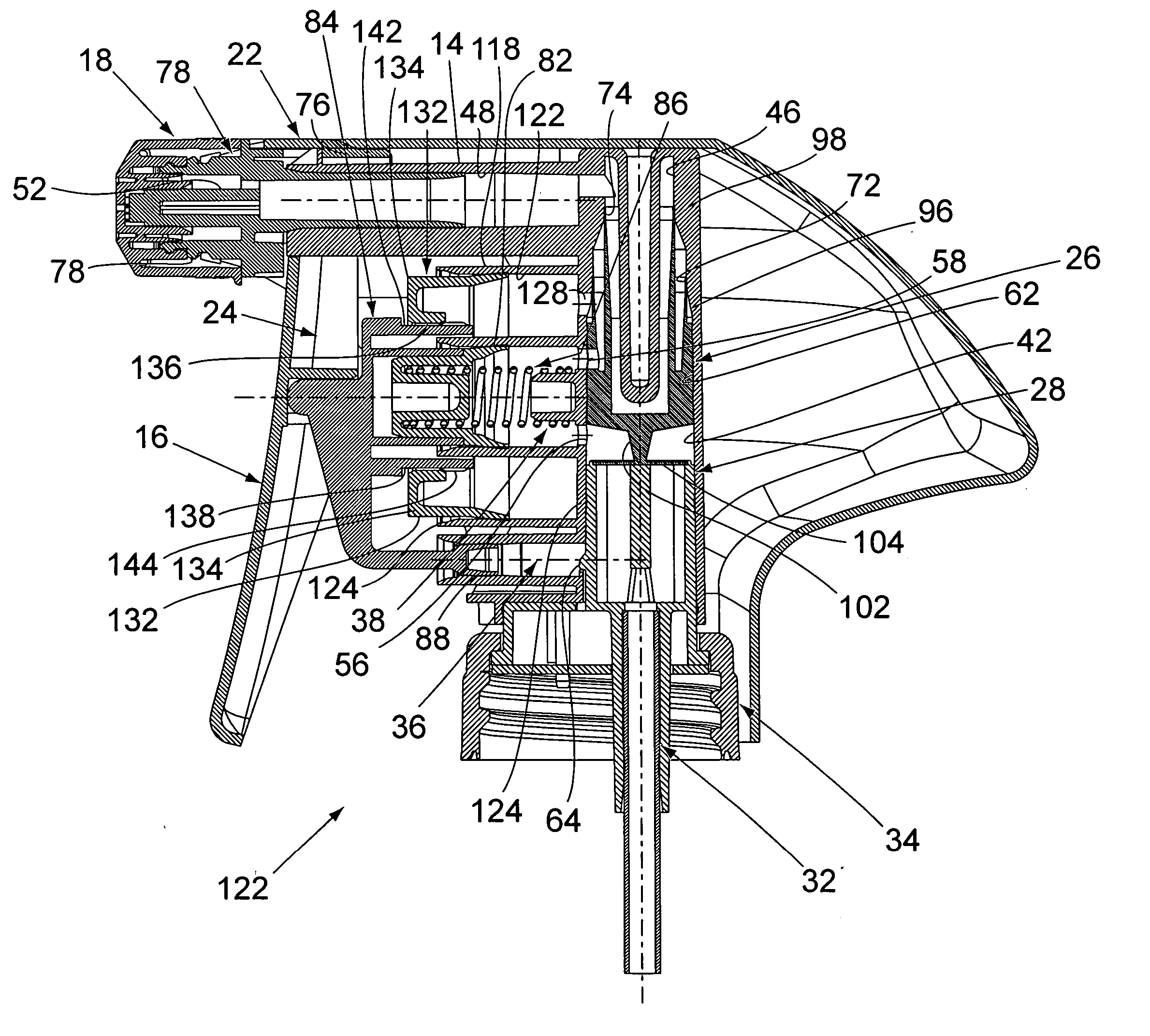
[0025] The air foaming trigger sprayer of the invention is similar in construction to the trigger sprayer disclosed in U.S. Pat. No. 6,641,003 B1, assigned to the assignee of the present invention and incorporated herein by reference. Because many of the component parts of the trigger sprayer disclosed in the above-referenced patent are employed in the construction of the trigger sprayer of the invention, these common component parts will first be generally described.
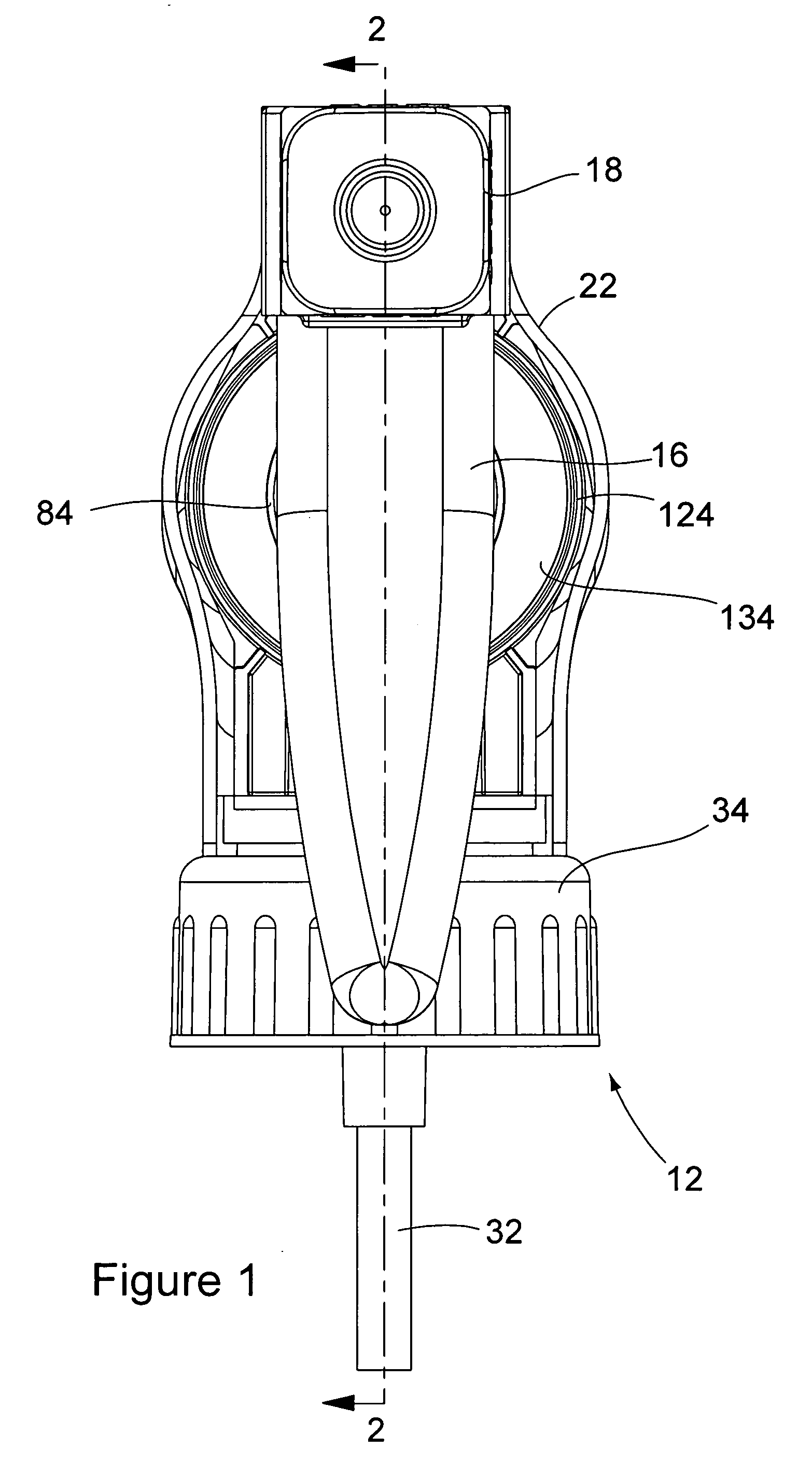
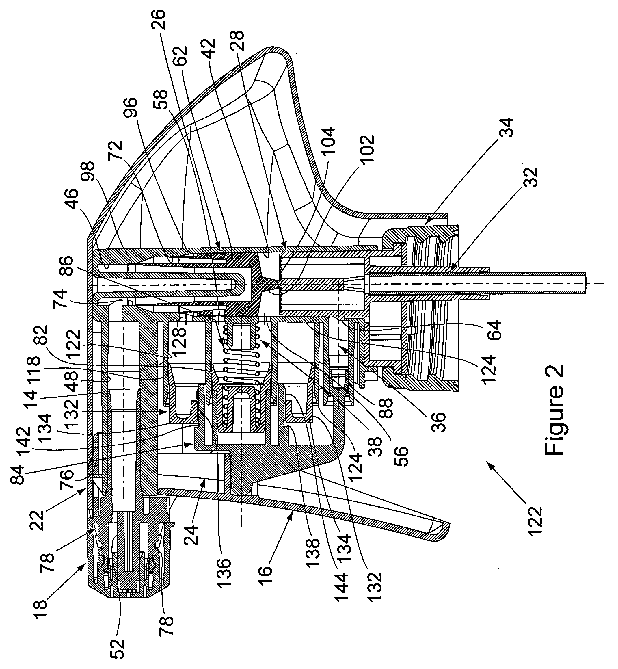
[0026]FIG. 3 shows the disassembled component parts of the trigger sprayer 12 that include the sprayer housing 14, the trigger 16, the discharge nozzle 18, the sprayer shroud 22, the liquid pump piston and vent piston assembly 24, the valve member 26, the valve seat insert 28 and the dip tube 32. Each of the component parts is constructed of a resilient plastic material, as is typical. However, the material employed in constructing the valve member 26 is more resilient and flexible than that of the other component part...
PUM
 Abstract
Description
Claims
Application Information