
Method of controlling rechargeable battery power and a power source apparatus

a technology of rechargeable batteries and power sources, applied in battery/fuel cell control arrangements, secondary cell servicing/maintenance, transportation and packaging, etc., can solve the problem of limited usable power

Inactive Publication Date: 2006-04-27
SANYO ELECTRIC CO LTD
View PDF3 Cites 91 Cited by
  • Summary
  • Abstract
  • Description
  • Claims
  • Application Information

AI Technical Summary

Benefits of technology

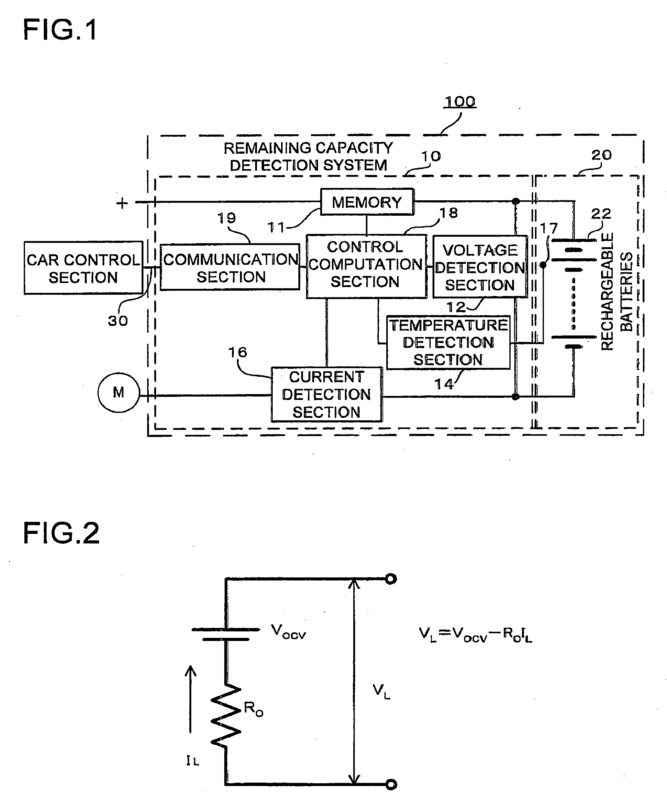
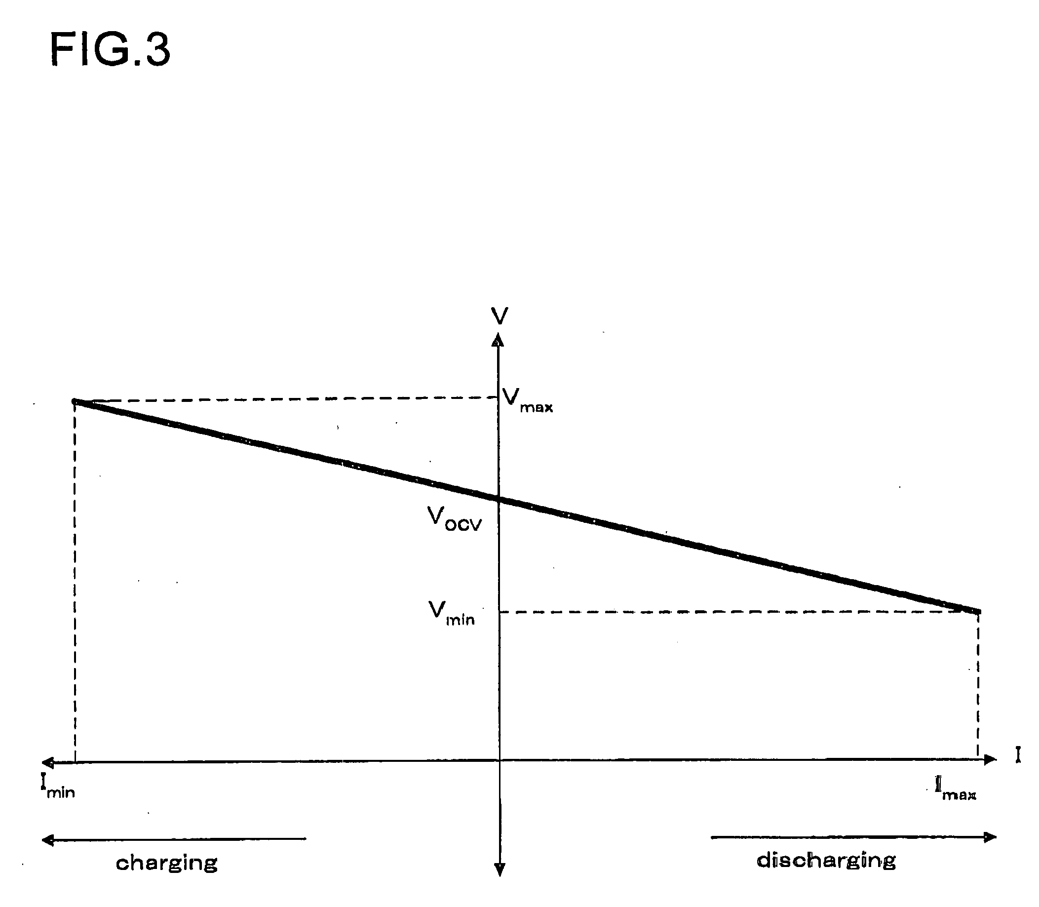
[0009] The second aspect of the method of controlling rechargeable battery power of the present invention, which is a method that also limits the amount of power used during charging and discharging, is to measure current flow IL and voltage VL during charging and discharging, and based on that, calculate rechargeable battery open circuit voltage VOC and internal resistance R0. From the straight line described by VL=VOCV−R0IL  (5) and from a prescribed minimum voltage Vmin to prevent over-discharging and / or a prescribed maximum voltage Vmax to prevent over-charging, a limiting discharging current Imax and / or a limiting charging current Imin are found from intersections on the straight line, and current flow through the rechargeable battery is controlled such that discharging current greater than or equal to Imax and / or charging current less than or equal to Imin does not flow. In this fashion, the amount of usable power can be limited considering factors such as the memory effect, and the rechargeable battery can be used to its maximum capability within the range of safe operation.
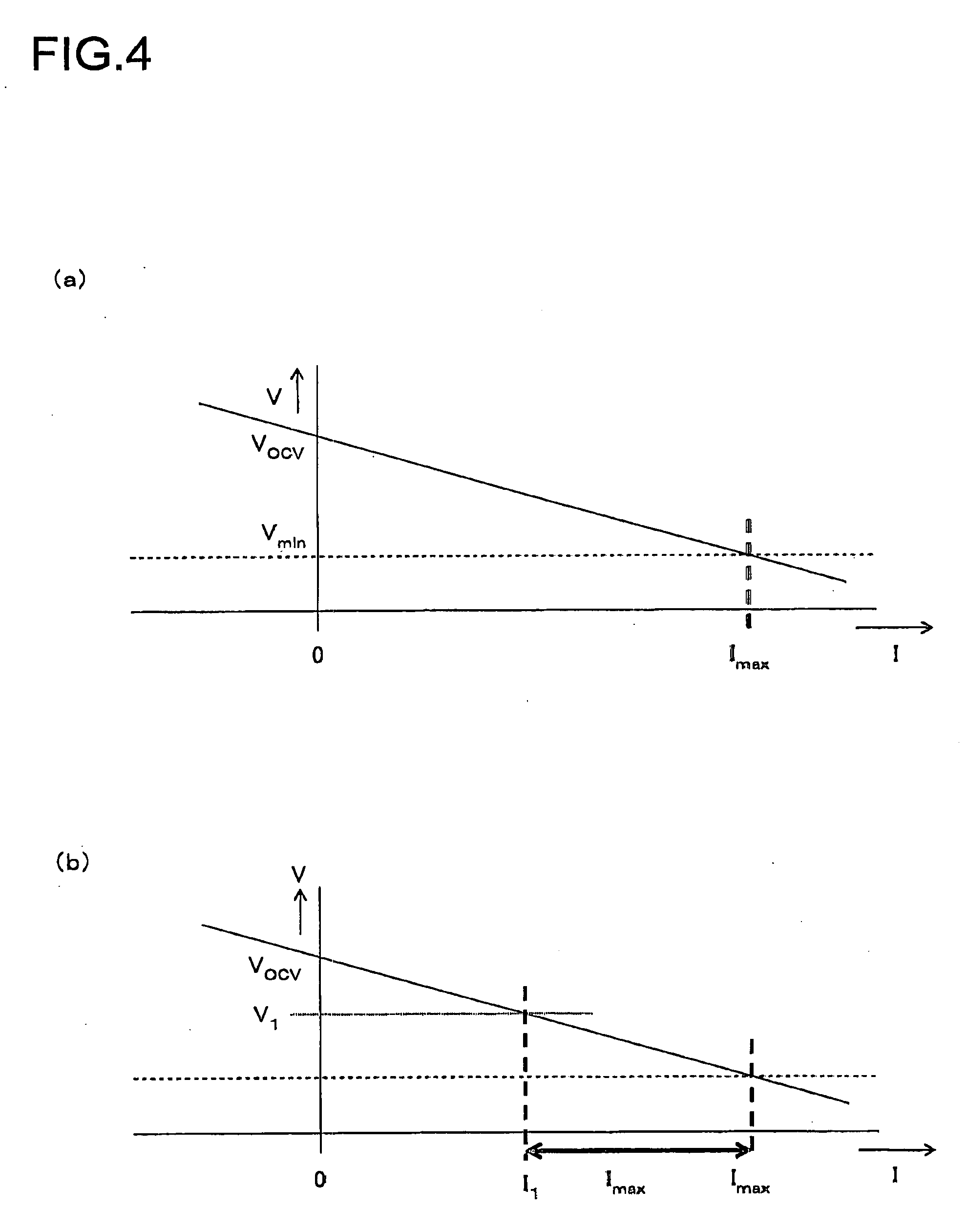
[0010] The third aspect of the method of controlling rechargeable battery power of the present invention is to periodically measure discharge voltage V1 and discharge current I1 during rechargeable battery discharge, and from the relation VOCV=VL+R0IL  (6) obtained from equation (5), update the value of VOCV. From equation (5) reflecting the updated VOCV and from a prescribed minimum voltage Vmin to prevent over-discharging, a limiting discharging current Imax is found from the intersection with Vmin on the straight line, and current flow through the rechargeable battery is controlled such that discharging current greater than or equal to Imax does not flow. In this fashion, since an upper limit on possibly increasing discharging current can be known at each point in time during rechargeable battery discharge, the value of discharging current can be limited within that range allowing rechargeable battery utilization with safety and to the maximum extent possible. In particular, the rechargeable battery can be used safely even when, as a result of discharge conditions, operation is off the straight line described above.
[0012] The fifth aspect of the method of controlling rechargeable battery power of the present invention is to compute maximum possible discharging power Plimd at any given time from the open circuit voltage VOCV and internal resistance R0 computed at that time during discharging, and from the equation Plimd=Vmin*(VOCV−Vmin) / R0.  (7) In this fashion, since an upper limit on the amount of power that can be output can be known at each point in time during rechargeable battery discharging, the amount of discharging power can be limited within that range allowing rechargeable battery discharging with safety and to the maximum extent possible.
[0013] The sixth aspect of the method of controlling rechargeable battery power of the present invention is to compute maximum possible charging power Plimc at any given time from the open circuit voltage VOCV and internal resistance R0 computed at that time during charging, and from the equation Plimc=Vmax*(Vmax−VOCV) / R0.  (8) In this fashion, since an upper limit on the amount of power that the rechargeable battery can be charged with can be known at each point in time during charging, the amount of charging power can be limited within that range allowing rechargeable battery charging with safety and to the maximum extent possible.
[0016] The method of controlling rechargeable battery power and power source apparatus of the present invention can compute the amount of maximum usable power without depending on rechargeable battery remaining capacity. In particular, power control based on remaining capacity can loose accuracy when the estimate of remaining capacity is in error. However, the present invention can perform stable power control regardless of the validity of the remaining capacity estimate, and the power source apparatus can be used effectively with a high degree of reliability.

Problems solved by technology

In this fashion, the amount of usable power can be limited considering factors such as the memory effect, and the rechargeable battery can be used to its maximum capability within the range of safe operation.

Method used


Image

  • Method of controlling rechargeable battery power and a power source apparatus
  • Method of controlling rechargeable battery power and a power source apparatus
  • Method of controlling rechargeable battery power and a power source apparatus

Examples


Embodiment Construction

[0025] The following describes forms of embodiments of the present invention based on the drawings. However, the forms of embodiments indicated below are for the purpose of concretely demonstrating technical concepts of the present invention, and the method of controlling rechargeable battery power and power source apparatus of this invention are not limited to the description below. Further, components cited in the claims are in no way specified by components in the forms of embodiments. Components shown in the drawings may have there size or positional relations exaggerated for the purpose of making the description clear. In the description below, components which are the same or are of the same material may be designated by the same name or label, and their detailed description may be suitably abbreviated. In addition, concerning elements that make up the present invention, a plurality of elements comprising the same components may be represented in the form of one component used...


PUM


Abstract

The method of controlling rechargeable battery power is a method that includes limiting the amount of usable power during rechargeable battery charging and discharging, determining a rechargeable battery current-voltage characteristic function based on rechargeable battery charging and discharging current flow and voltage, finding a limiting discharging current Imax and / or a limiting charging current Imin from a prescribed minimum voltage Vmin to prevent over-discharging and / or a prescribed maximum voltage Vmax to prevent over-charging and their intersection with the current-voltage characteristic function, and controlling current such that discharging current greater than or equal to Imax and / or charging current less than or equal to Imin does not flow through the rechargeable batteries. In this fashion, the amount of usable power can be limited considering factors such as the memory effect, and the rechargeable battery can be used to its maximum capability within the range of safe operation.

Description

BACKGROUND OF THE INVENTION [0001] 1. Field of the Invention [0002] This invention relates to a method of controlling the amount of rechargeable battery power and to a power source apparatus, and for example, relates to a method to limit the amount of electric power from a rechargeable battery included in a power source apparatus for powering a motor to drive a car and to the power source apparatus. [0003] 2. Description of the Related Art [0004] A power source apparatus can increase output current by increasing the number of power source modules that connect batteries or battery cells in series or parallel. It can raise output voltage by increasing the number of series connected power source modules. In particular, a configuration that connects a plurality of batteries in series to increase output can be adopted by a power source apparatus used in applications that require high output such as cars or automobiles, bicycles, and tools. For example, a high current, high output power s...

Claims


Application Information

Patent Timeline
IPC IPC(8): H02J7/00
CPCB60L11/1811B60L11/1862H02J7/0057H02J7/0063Y02T90/14Y02T10/7044Y02T10/705Y02T90/127Y02T10/7005Y02T10/7072B60L53/20H02J7/0069B60L58/15Y02T10/70H02J7/00714H02J7/007194H02J7/007182Y02E60/10H01M10/44Y02T90/12
Inventor YAMAUCHI, YUTAKA
Owner SANYO ELECTRIC CO LTD
Learn More