E-field mapping

a technology of electric field and electric field, applied in the direction of electrical measurement, measurement devices, instruments, etc., can solve the problems of requiring relatively complicated analysis and measurement equipments, affecting the accuracy of eis, so as to reduce costs and complexity, the effect of simple and low-cos

Inactive Publication Date: 2006-04-27
ACREO
View PDF4 Cites 12 Cited by
  • Summary
  • Abstract
  • Description
  • Claims
  • Application Information

AI Technical Summary

Benefits of technology

[0032] According to one particular embodiment, the analyzing means is operable to determine optical centroids of color density and to detect changes in optical appearance in terms of movements of said centroids. Analyzing movements of the centroids has proven to be a straightforward and effective way of quantifying the electric field. The centroids can be measured for a specific frequency of light, or for a set of frequencies. A particular advantage of using this approach is that conventional imaging and image analyzing equipment and methods can be employed, thereby reducing costs and complexity.
[0033] The sensor device is thus advantageous in that it provides a straightforward and low-cost device for measuring electric fields, and possibly also ion concentrations and mobilities, in a charge carrying medium. Depending on the number of sensor elements, the measurements can be restricted to a course, large-scale level, requiring only a few sensor elements, or it can be performed on a more detailed and refined level, requiring a larger number of sensor elements. In other words, aggregating a number of local, micro-level measurements provides for a macro-level measurement of the electric field in the ion conductive medium.

Problems solved by technology

However, measurement of the electric field distribution within charge carrying media is typically performed in relatively cumbersome fashions.
EIS is a very powerful tool, but requires relatively complicated analysis and measurement equipments.
Interpreting the results of solid and gel electrolytes can be especially difficult due to the flexing of the supporting structure.

Method used


Image

  • E-field mapping
  • E-field mapping
  • E-field mapping

Examples


Embodiment Construction

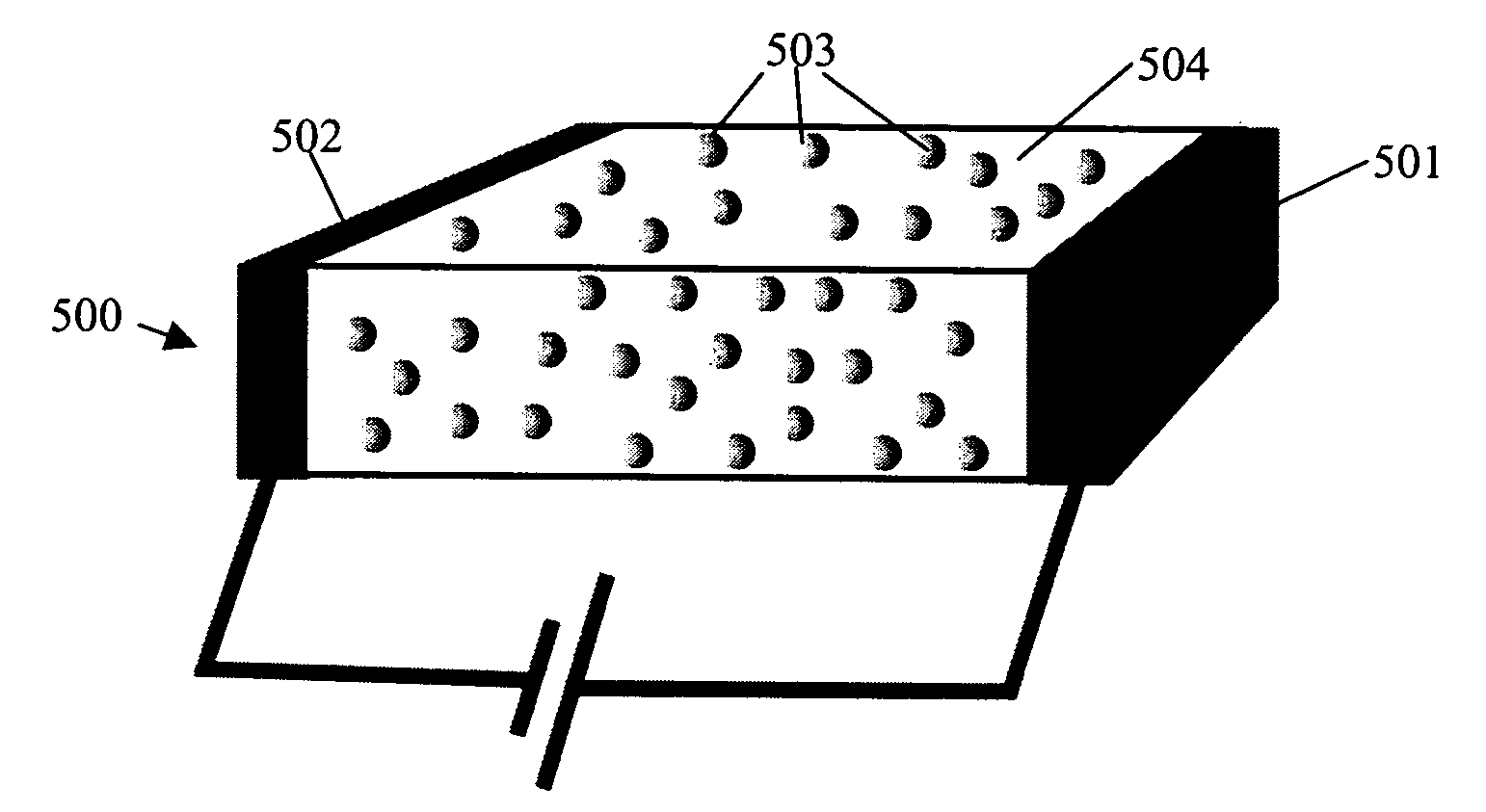
[0058] In preferred embodiments, the sensor element comprises, as electrochemically active material, an electrochromic polymer which is electrically conducting in at least one oxidation state, and optionally also comprises a polyanion compound such as poly(styrenesulfonate) (PSS). Electrochromic polymers for use in the sensor element are preferably selected from the group consisting of electrochromic polythiophenes, electrochromic polypyrroles, electrochromic polyanilines, electrochromic polyisothianaphthalenes, electrochromic polyphenylene vinylenes and copolymers thereof, such as described by J C Gustafsson et al in Solid State Ionics, 69, 145-152 (1994); Handbook of Oligo- and Polythiophenes, Ch 10.8, Ed D Fichou, Wiley-VCH, Weinhem (1999); by P Schottland et al in Macromolecules, 33, 7051-7061 (2000); Technology Map Conductive Polymers, SRI Consulting (1999); by M Onoda in Journal of the Electrochemical Society, 141, 338-341 (1994); by M Chandrasekar in Conducting Polymers, Fund...


PUM


Abstract

The present invention provides a sensor device for measuring an electric field in a charge carrying medium. To this end, the sensor device defines a sensor space that is arranged to receive the charge carrying medium, and that comprises terminals for applying an electric field across the sensor space. Furthermore, sensor elements are arranged spatially separated in the sensor space. The sensor elements are operable to perform electrochemistry in response to the electric field and to change optical appearance upon said electrochemistry. Thereby electric field present in said sensor space is detectable from an optical appearance of said sensor elements.

Description

TECHNOLOGICAL FIELD OF THE INVENTION [0001] The present invention relates to devices and methods for measuring electric fields in a charge carrying medium. TECHNOLOGICAL BACKGROUND [0002] Measurement of local electric fields in a charge carrying medium is important in many applications. For example, the stability, selectivity, and efficiency of polymer electrolytes in fuel cells (PEFCs), polymer light emitting electrochemical cells (PLEC), batteries, and electrochemical sensors depend on the electric field distribution within the electrolyte. However, measurement of the electric field distribution within charge carrying media is typically performed in relatively cumbersome fashions. [0003] Furthermore, the conductivity of electrolytes are conventionally evaluated as bulk properties using techniques such as Electronic Impedance Spectroscopy (EIS). EIS is a very powerful tool, but requires relatively complicated analysis and measurement equipments. Interpreting the results of solid an...

Claims


Application Information

Patent Timeline
Patent Type & Authority Applications(United States)
IPC IPC(8): G01R27/00
CPCG01R29/14
Inventor BERGGREN, MAGNUSROBINSON, NATHANIEL D.SAID, ELIASNILSSON, DAVIDSVENSSON, PER-OLOFHALL, JESSICA
Owner ACREO
Why Eureka
Try Eureka