Image-taking apparatus and control method of image-taking apparatus

a control method and image-taking technology, applied in the field of exposure control techniques, can solve the problems of inability to finish the accumulation operation simultaneously in all pixels, inability to prevent the occurrence of smear, and inability to take a still image of a moving subject with a cmos image sensor

Active Publication Date: 2006-04-27
CANON KK
View PDF6 Cites 51 Cited by
  • Summary
  • Abstract
  • Description
  • Claims
  • Application Information

AI Technical Summary

Benefits of technology

[0008] According to at least a preferable embodiment, the present invention provides an image-taking apparatus having an image-pickup device which accumulates charge in accordance with an amount of light received thereon, a light-shielding device which changes a light-shielded area in the image-pickup device by causing a light-shielding blade to travel, the light-shielding blade shielding a light-receiving surface of the image-pickup device, a scan circuit which performs first scan for staring accumulation of charge for each area of the image-pickup device and performs second scan for reading the accumulated charge for each area of the image-pickup device, and a control circuit which calculates a travel characteristic of the light-shielding device based on an amount of first charge accumulated in a time period between one of the first and second scans and the travel of the light-shielding device.

Problems solved by technology

However, the occurrence of smear cannot be prevented since luminous flux reaches the PS-CCD even in a short time period from the completion of the charge accumulation operation in the PS-CCD to shielding of light by the mechanical shutter.
The CMOS image sensor of the XY address type, however, accumulates charge in different timings for different rows as a so-called rolling shutter, and thus cannot finish the accumulation operation simultaneously in all pixels.
If exposure control is attempted by controlling the charge accumulation time in the CMOS image sensor, the accumulation period in the first row of scan lines is different from that in the final row approximately one frame, so that it is contemplated that the CMOS image sensor is not suitable to take a still image of a moving subject.

Method used


Image

  • Image-taking apparatus and control method of image-taking apparatus
  • Image-taking apparatus and control method of image-taking apparatus
  • Image-taking apparatus and control method of image-taking apparatus

Examples


embodiment 1

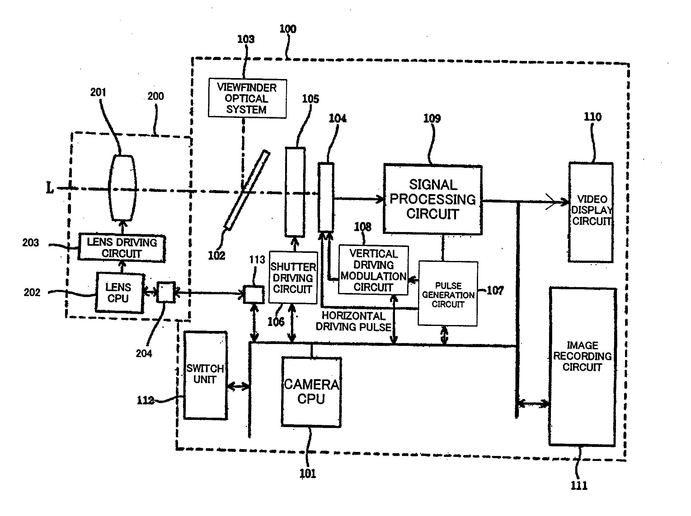
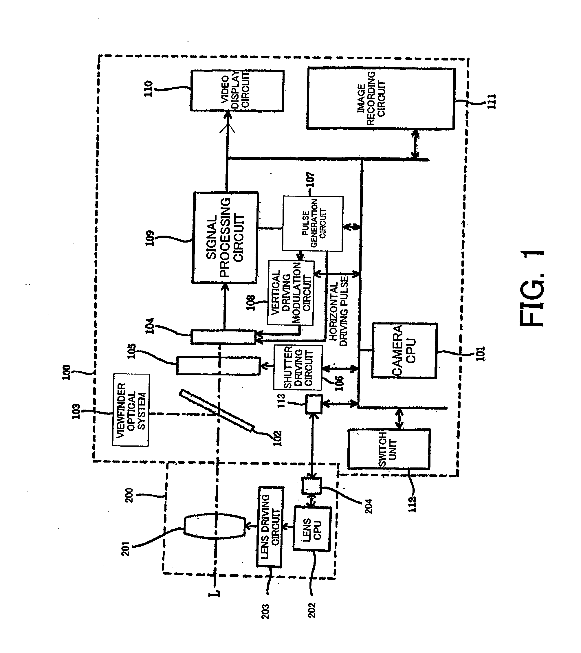
[0028]FIG. 1 shows the structure of an image-taking system according to Embodiment 1 of the present invention. The image-taking system according to Embodiment 1 has a camera body 100 serving as an image-taking apparatus and an interchangeable lens apparatus 200 which is mounted on the camera body 100. The interchangeable lens apparatus 200 may not be removably mounted on the camera body 100 and it may be integrally formed with the camera body 100.

[0029] First, description will be made of the structure in the interchangeable lens apparatus 200. Reference numeral 201 shows an image-taking lens which is movable in the direction of an optical axis L. While FIG. 1 shows only one lens for simplicity, the lens apparatus 200 includes a plurality of lens units.

[0030] Reference numeral 202 shows a lens CPU, and 203 a lens driving circuit. The lens CPU 202 controls the position of the image-taking lens 201 through the lens driving circuit 203. The lens CPU 202 communicates with a camera CPU ...

embodiment 2

[0103] Next, description will be made of Embodiment 2 centered on differences from Embodiment 1. The basic structure of an image-taking system according to Embodiment 2 is substantially the same as that of the image-taking system according to Embodiment 1 except that a shutter apparatus 105 of a camera body 100 has no front blade in the image-taking system in Embodiment 2.

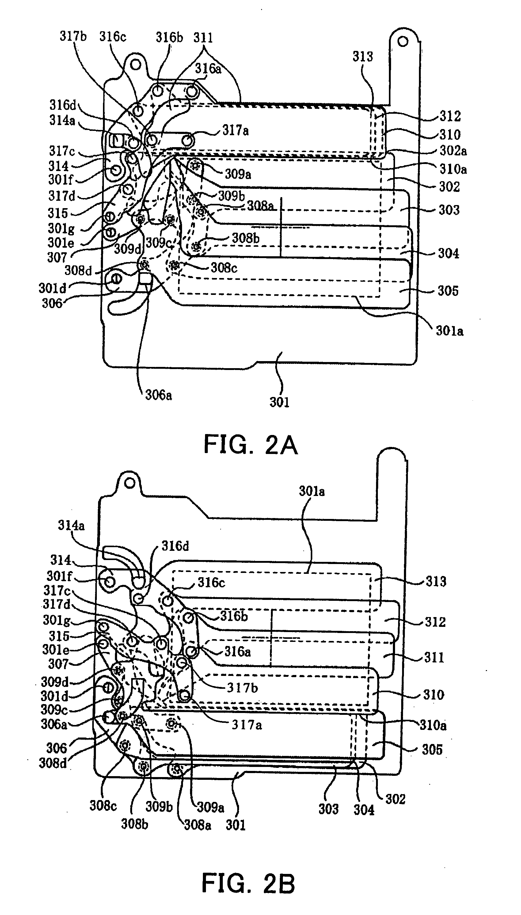
[0104]FIG. 10 shows the structure of the shutter apparatus 105 according to Embodiment 2 of the present invention. It differs from the shutter apparatus in Embodiment 1 in that it does not have a front curtain slit forming blade 302, a first front blade 303, a second front blade 304, a third front blade 305, a first arm 306 for the front blade, a second arm 307 for the front blade, caulked dowels 308a to 308d, or 309a to 309d which constitute the front blade. In other words, the shutter apparatus 105 of Embodiment 2 only has a rear blade. Specifically, it only has the rear blade formed by a rear blade slit forming...


PUM


Abstract

The present invention provides an image-taking apparatus having an image-pickup device which accumulates charge in accordance with an amount of light received thereon, a light-shielding device which changes a light-shielded area in the image-pickup device by causing a light-shielding blade to travel, the light-shielding blade shielding a light-receiving surface of the image-pickup device, a scan circuit which performs first scan for staring accumulation of charge for each area of the image-pickup device and performs second scan for reading the accumulated charge for each area of the image-pickup device, and a control circuit which calculates a travel characteristic of the light-shielding device based on an amount of first charge accumulated in a time period between one of the first and second scans and the travel of the light-shielding device.

Description

BACKGROUND OF THE INVENTION [0001] The present invention relates to an exposure control technique which uses both an electronic shutter function of controlling the timing of start of charge accumulation or reading of charge in an image-pickup device and a mechanical shutter function of covering a light-receiving surface of the image-pickup device with a light-shielding blade. [0002] An image-taking apparatus such as a digital camera has a CCD of a progressive scan type (hereinafter referred to as PS-CCD) as an image-pickup device. With the PS-CCD used as the image-pickup device, the image-taking apparatus can control the exposure state of image data provided from output of the image-pickup device by controlling charge accumulation time from elimination of charge to transfer of accumulated charge. When the PS-CCD is used as the image-pickup device, the image-taking apparatus can adjust the charge accumulation time without using any mechanical shutter, but it is preferable to include ...

Claims


Application Information

Patent Timeline
Patent Type & Authority Applications(United States)
IPC IPC(8): H04N5/335G03B9/36H04N5/238H04N5/353H04N5/359H04N5/374H04N101/00
CPCH04N5/2352H04N5/2353H04N23/72H04N23/73
Inventor HARADA, YOSHIHITO
Owner CANON KK
Why Eureka
Try Eureka