Connector and connector assembly

a technology of connectors and connectors, applied in the direction of coupling device connections, coupling parts engagement/disengagement, electrical apparatus, etc., can solve the problems of complex shapes of housings and levers, difficult to manipulate an operable portion as thin as the rest, and large enlarge the entire lever-type connector. , to achieve the effect of simplifying the shape of connectors

Active Publication Date: 2006-04-27
SUMITOMO WIRING SYST LTD
View PDF6 Cites 8 Cited by
  • Summary
  • Abstract
  • Description
  • Claims
  • Application Information

AI Technical Summary

Benefits of technology

[0010] The invention relates to a connector with a housing and a movable member mountable on the housing. The movable member is configured to display a cam action together with cam follower of a mating housing. More particularly, the cam follower can enter a cam groove of the movable member after the movable member is displaced from a mount position to a standby position. The housing then can be connected with the mating housing by displacing the movable member from the standby position to a connection position. A return preventing means is provided for p

Problems solved by technology

Thus, the housings and the lever have complicated shapes.
However, this enlarges the entire lever-type connector.
However, the operable portion of the plat

Method used


Image

  • Connector and connector assembly
  • Connector and connector assembly
  • Connector and connector assembly

Examples


Embodiment Construction

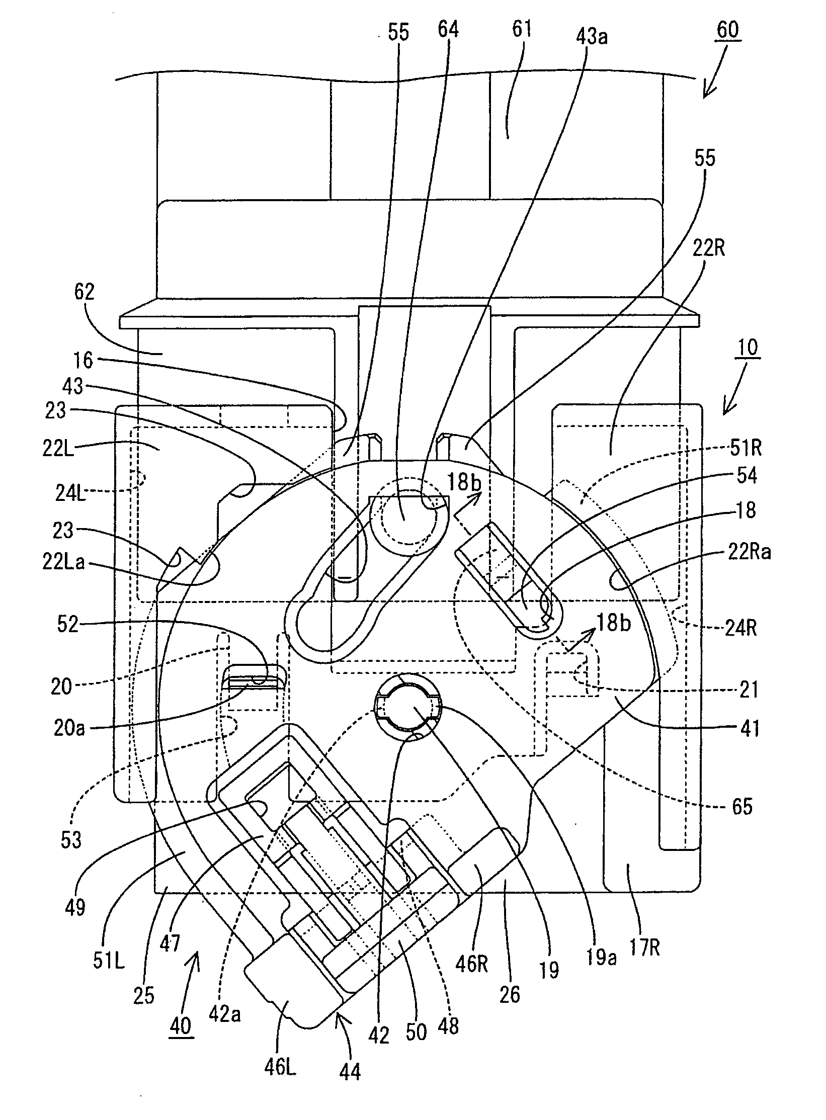
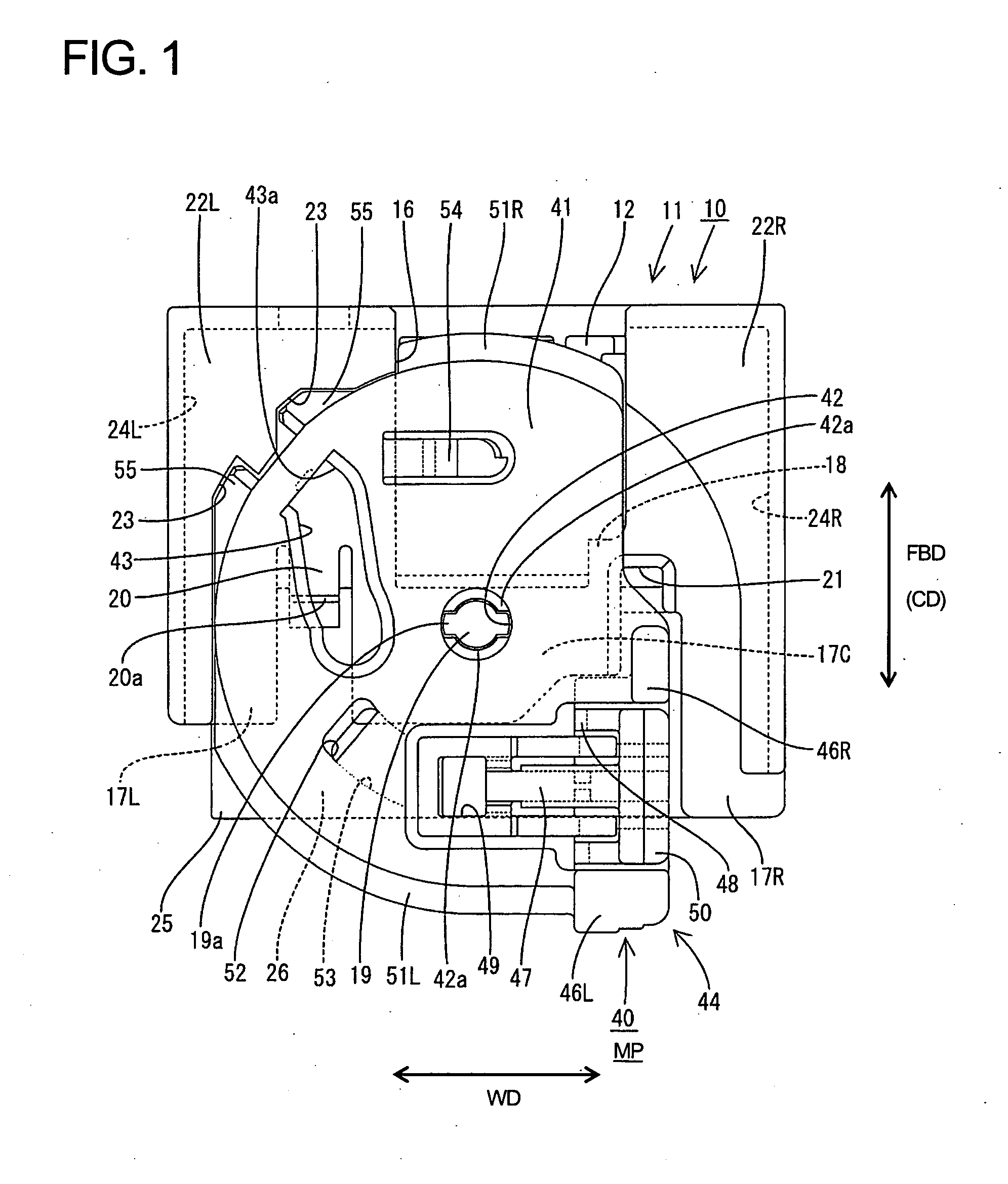
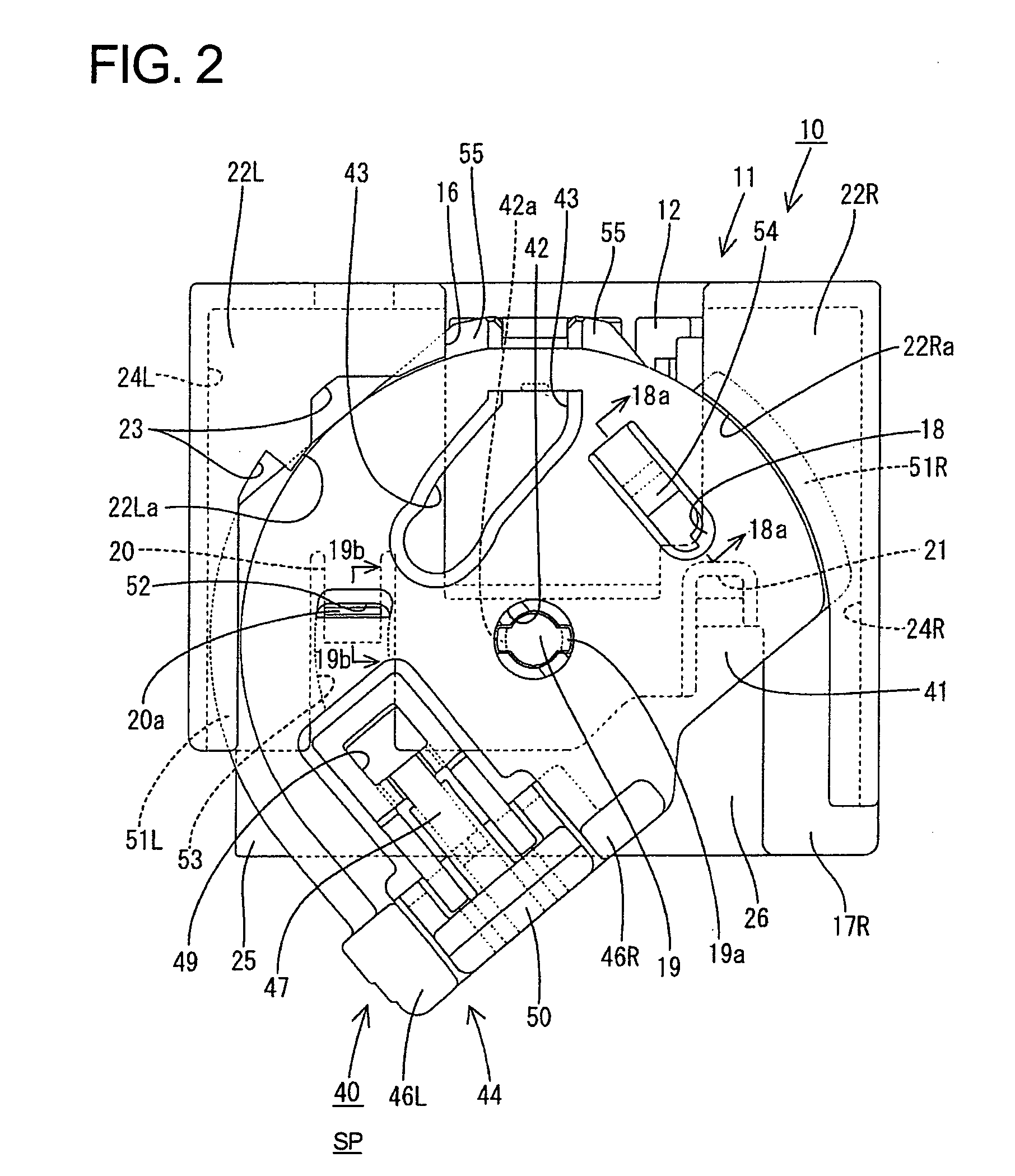
[0047] A connector according to the invention is described with reference to FIGS. 1 to 25. The connector has a first housing 10 and a second housing 60 that can be connected with and separated from each other by a movable member. Ends of the housings 10 / 60 to be connected with the other are referred to as the front.

[0048] The first housing 10 is made e.g. of a synthetic resin and is a flat generally rectangular block that is a shorter along a height direction HD than along forward and backward directions FBD and transverse direction TD. The first housing 10 has a terminal accommodating portion 11 and a seal tower 25.

[0049] The terminal accommodating portion 11 has a wide rectangular main portion 12 and a tubular fitting 13 that surrounds the main portion 12. A forwardly open fitting recess 14 is formed between the outer periphery of the main portion 12 and the inner periphery of the tubular fitting 13. Cavities 15 are formed in a substantially transverse row in the main portion 1...


PUM


Abstract

A return preventing portion flexible locking piece (20) and return preventing portion (52) for preventing a lever (40) from returning from a standby position to a mount position and a locking means flexible locking piece (20) and lock arm (47) for locking the lever (40) at a connection position are provided. The flexible locking piece (20) return preventing means, locking means of a first housing (10) one member is engaged with the lock arm (47) of the lever (40) (other member), whereby the lever (40) is locked at the connection position. The shape of the first housing (10) can be simplified since it is not necessary to provide the first housing (10) with a locking means for exclusive use in addition to the flexible locking piece (20).

Description

BACKGROUND OF THE INVENTION [0001] 1. Field of the Invention [0002] The invention relates to a connector with a movable member to facilitate connection with a mating connector. [0003] 2. Description of the Related Art [0004] U.S. Pat. No. 5,6121,703 discloses a connector with a lever mounted on a first housing. The lever can be held temporarily at a standby position so that cam followers of a second housing can enter cam grooves of the lever. The housings are connected by displacing the lever to a connection position. The connector includes means for temporarily holding the lever at the standby position, a return preventing means for preventing the lever from returning from the standby position to the mount position, and a locking means for locking the lever at the connection position. [0005] The means for preventing the lever from returning from the standby position to the mount position and the locking means for locking the lever at the connection position are provided separately ...

Claims


Application Information

Patent Timeline
IPC IPC(8): H01R13/62
CPCH01R13/5219H01R13/62938H01R13/6295H01R13/62955
Inventor FUKATSU, YUKIHIRO
Owner SUMITOMO WIRING SYST LTD
Why Eureka
Try Eureka