Wireless interference detector

a detector and wireless technology, applied in the field ofsignal processors, can solve the problems of difficult identification of the source of any radio frequency signal, large difficulty in providing interpretation of transmission source, and limited ability of known signal processors to provide interpretation of transmission sources, etc., and achieve the effect of being easily transported by hand

Inactive Publication Date: 2006-04-27
ROSE-HULMAN INSTITUTE OF TECHNOLOGY
View PDF7 Cites 28 Cited by
  • Summary
  • Abstract
  • Description
  • Claims
  • Application Information

AI Technical Summary

Benefits of technology

[0011] Advantageously, the detector includes a display for displaying the identities of the local RF sources so that scope interpretation and RF signal knowledge, such as that required for operating oscilloscopes and spectrum analyzers, is not required to identify a known source of a received RF

Problems solved by technology

However, the apparatus is dependent on the transient turn-on characteristics of the transmitter and does not receive and identify transmitters based on signal characteristics associated with a transmitter already on the air.
One problem with prior signal processors is that they provide raw data on a display which must

Method used


Image

  • Wireless interference detector
  • Wireless interference detector
  • Wireless interference detector

Examples


Embodiment Construction

[0020] The embodiment disclosed below is not intended to be exhaustive or limit the invention to the precise form disclosed in the following detailed description. Rather, the embodiment is chosen and described so that others skilled in the art may utilize its teachings.

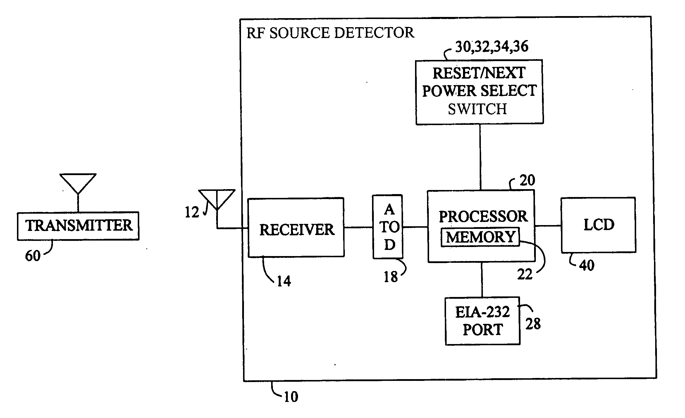
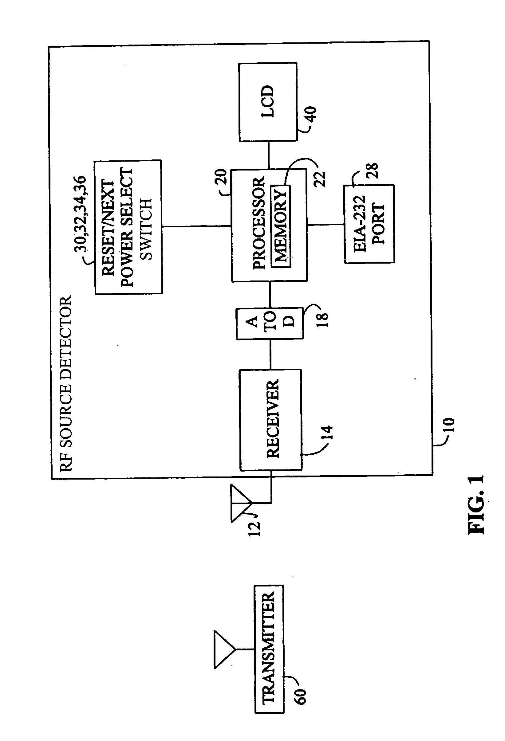
[0021] Referring to FIG. 1, an exemplary embodiment of RF source detector 10 is shown. RF source detector 10 detects the local sources of RF signals or interference, such as RF transmitter source 60, and receives and analyzes RF signals in order to determine the identities or types of RF sources 60.

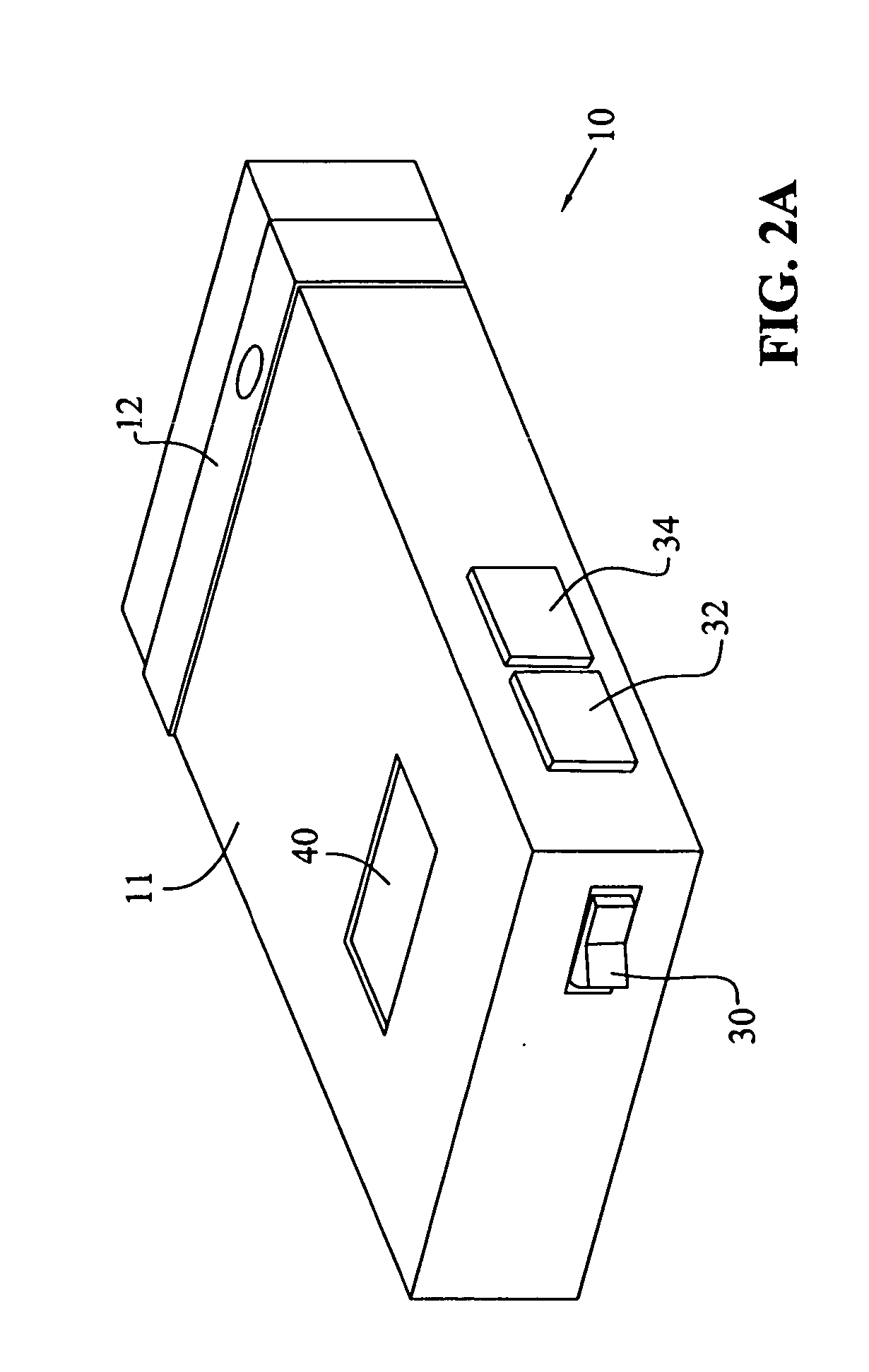
[0022] RF source detector 10 includes antenna 12, receiver 14, and analog-to-digital converter (A / D converter) 18, which receive and provide digital samples of RF signals to processor 20. Processor 20 includes memory 22 and is coupled to user interfaces including liquid crystal display (LCD) 40, reset switch 36, next switch 32, power switch 30, select switch 34, and communications port 28.

[0023] Referring to FIGS. 2A and...


PUM


Abstract

A radio frequency (RF) source detector detects and analyzes RF signals in order to determine the source of interference. The source detector is useful for installing and troubleshooting a wireless local area network (WLAN) or similar communication devices. The detector includes a receiver to receive RF signals from unknown RF sources, a processor for determining the level and characteristics of the RF signals and for determining the identities of unknown RF sources, and a display on which the processor displays the identities of the RF sources.

Description

BACKGROUND OF THE INVENTION [0001] 1. Field of the Invention [0002] The present invention relates to signal processors for detecting and analyzing radio frequency transmissions and interference. [0003] 2. Description of the Related Art [0004] Oscilloscopes produce an instantaneous trace of a received signal on a display screen, such as a cathode ray tube. The instantaneous trace is generally displayed in terms of amplitude versus time and corresponds to variations in voltage or current over time, or, in the case of receiving a radio frequency transmission, corresponds to variations in amplitude and frequency over time. When displaying radio frequency signals, oscilloscopes therefore provide a display of the raw signal showing variations over time. [0005] Signal and spectrum analyzers provide a display showing the power distribution of a signal across a range of frequencies. The display therefore shows the frequency or frequencies contained within the received signal. For reception o...

Claims


Application Information

Patent Timeline
IPC IPC(8): H04B17/00H04B1/26
CPCH04W16/14H04W24/00H04B17/345H04B17/23H04W84/12
Inventor OSBURN, JAMES P.
Owner ROSE-HULMAN INSTITUTE OF TECHNOLOGY
Why Eureka
Try Eureka