

Constant velocity universal joint system
- Summary
- Abstract
- Description
- Claims
- Application Information
AI Technical Summary
Benefits of technology
Problems solved by technology
Method used
Image

Examples
Embodiment Construction
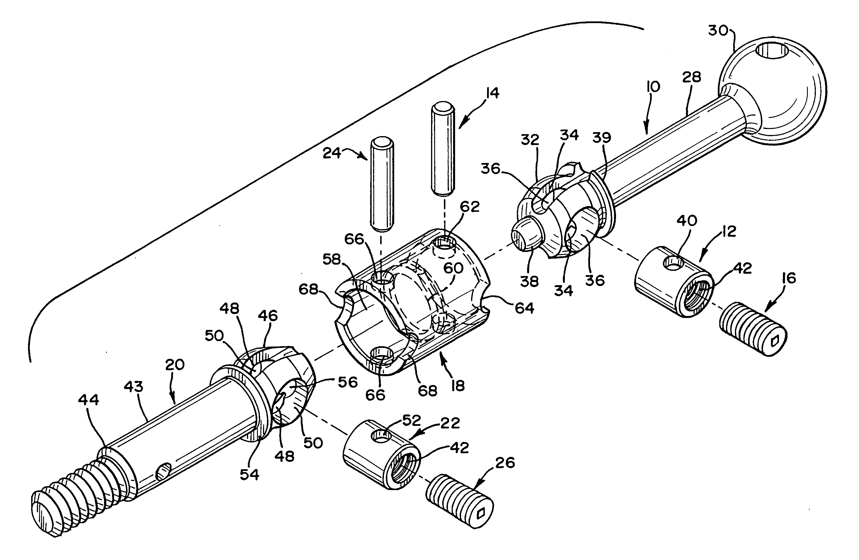
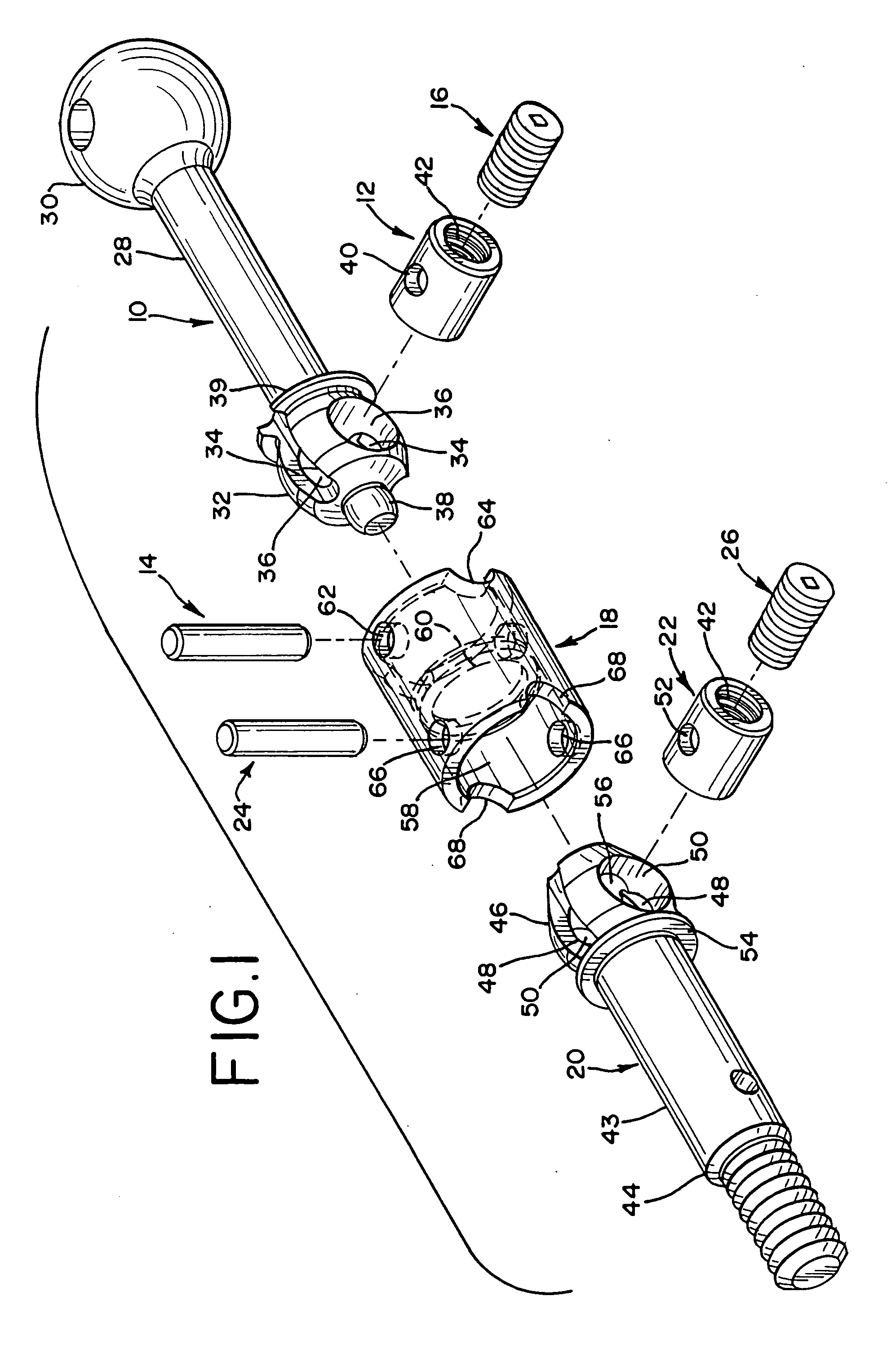
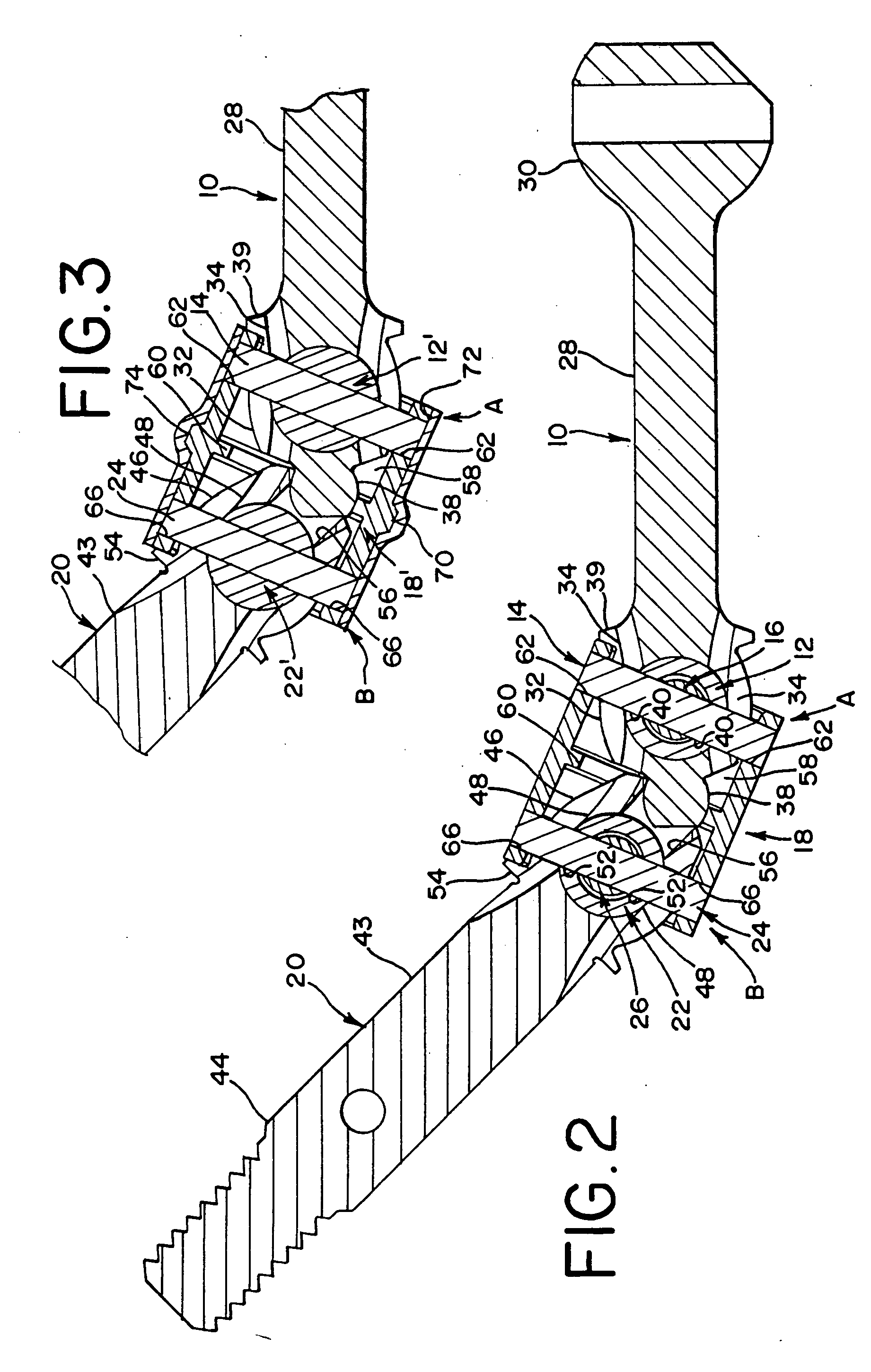
[0023] As shown in FIGS. 1 and 2, one preferred embodiment of constant velocity universal joint system of the present invention generally comprises the following components: 1) an input universal joint A comprising an input shaft 10, an input coupling 12, an input drive pin 14, and an input set screw 16; 2) a coupler 18; and 3) an output universal joint B comprising an output shaft 20, an output coupling 22, an output drive pin 24, and an output set screw 26.
[0024] The input shaft 10 includes an elongate shaft portion 28 which is formed at one end with a suitable coupling link 30 for coupling the input shaft 10 to a drive axle (not shown) of a vehicle or other device for transmitting rotational mechanical power to the system. The coupling link 30 may take any one of a number of desired forms and may be formed integrally with the elongate shaft portion 28 as shown or may be attached to the shaft portion 28 as a distinct element.
[0025] The input shaft 10 has a generally spherical he...
PUM
 Abstract
Description
Claims
Application Information