
Method of generation of face enveloping gears

Inactive Publication Date: 2006-05-04
FLEYTMAN YAKOV
View PDF29 Cites 15 Cited by
  • Summary
  • Abstract
  • Description
  • Claims
  • Application Information

AI Technical Summary

Benefits of technology

[0015] Simplified manufacturing of enveloping pinion machined by rotating cutter having generating elements rotating about respective cutter-head axis consisting in positioning the cutter in tangential relation relative to meshing of said enveloping worm thread having smallest pitch diameter with said face gear teeth and then turning of said rotating cutter relative to axis of theoretical generating gear for enveloping pinion and turning relative to the enveloping pinion around the axis of rotation of enveloping pinion until generating of a thread with the biggest pitch diameter. Relative turning to the enveloping pinion is faster in ratio between meshed face enveloping gears.
[0016] Above described manufacturing could be used for independent manufacturing of concave or convex surfaces of the enveloping pinion threads and face gear teeth or for simultaneous manufacturing of concave and convex thread surfaces or face gear teeth surfaces. Rotating tool can have cutting blades for machining or an abrasive surface for finishing. Using rotating tool like face milling or face hobbing allows for the use of very productive technology that was developed for standard spiral bevel and hypoid gears. The cost of production of enveloping face gears can be reduced.

Problems solved by technology

In existing enveloping worm and worm gear transmission it was not possible to use plunge feeding because gears became just index drives and were not efficient gears for transmission power.

Method used


Image

  • Method of generation of face enveloping gears
  • Method of generation of face enveloping gears
  • Method of generation of face enveloping gears

Examples


Embodiment Construction

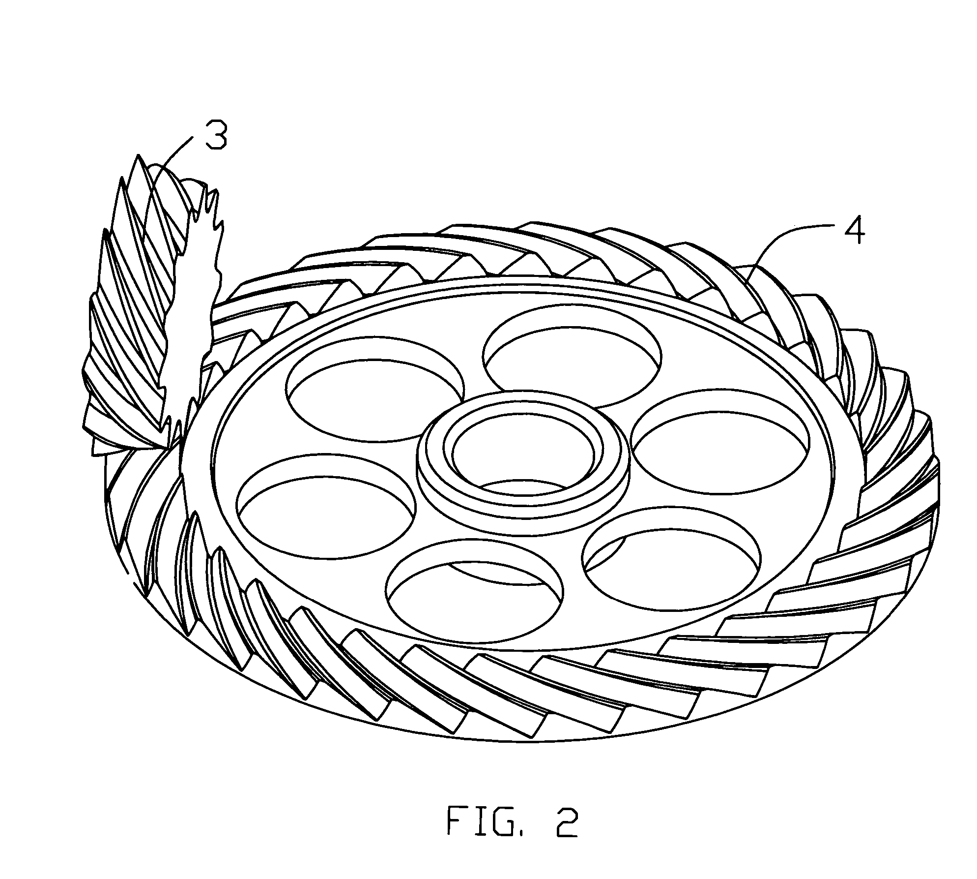
[0043] The following discussion relating to FIGS. 1-22 provides a detailed description of the unique method for manufacturing face enveloping pinion and face gear that can be utilized with the present invention.

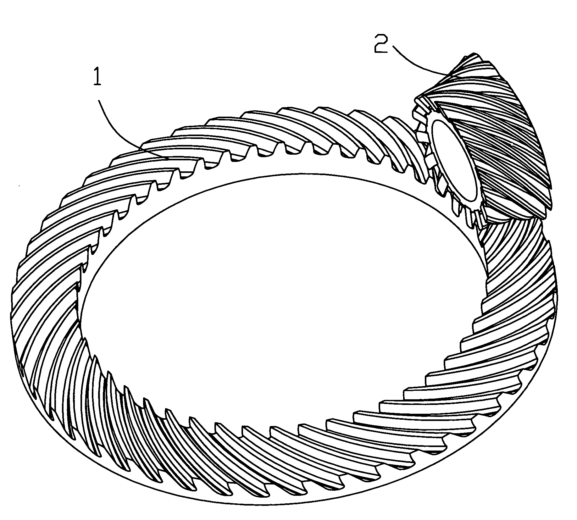
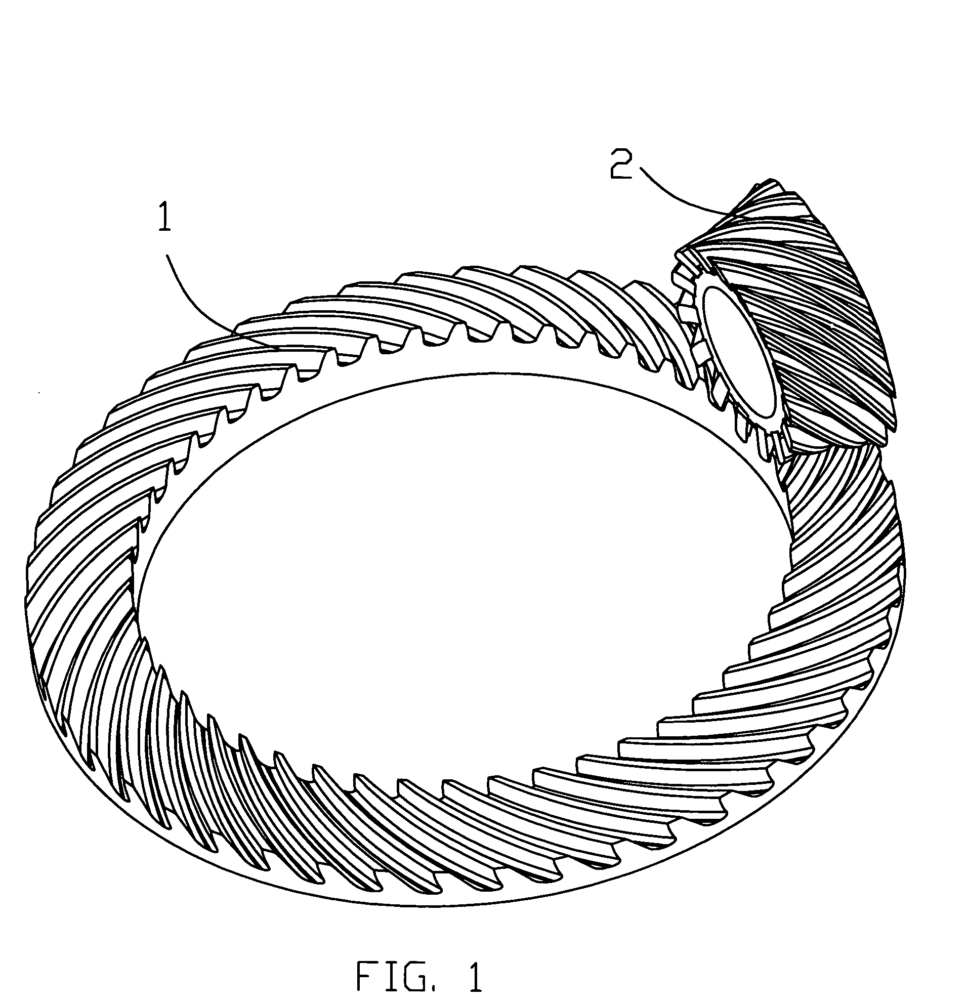
[0044]FIG. 1 is an isometric view of face gear 1 in mesh with enveloping worm 2 as a pinion. Face enveloping gears are a new type of right angle gears (U.S. patent application Ser. No. 10 / 435,143 filed May 9, 2003). Said enveloping worm 2 has at least one thread that is engaged by at least one tooth of said face gear 1 wherein said enveloping worm 2 is placed into face arrangement with said face gear 1. In these face enveloping gears the enveloping worm 2 could have any design, however, it is preferred that the enveloping worm is utilized for standard enveloping or double enveloping worm / worm gear transmission. Another name for double enveloping worm / worm gears is globoid gears. Face enveloping gears are using worm threads with less than one revolution or 180 or less degrees...


PUM

PropertyMeasurementUnit
Diameteraaaaaaaaaa
Widthaaaaaaaaaa
Angular velocityaaaaaaaaaa

Abstract

Face enveloping gears are machined by face milling type cutting tool or gear shaper. This process includes the following steps: positioning of the cutting tool in tangential relation relative to the meshing enveloping pinion thread with face gear by the smallest pitch diameter of threads with face gear teeth; turning rotating cutter relative to axis of rotation of an imaginary enveloping wheel until generating tooth is on the outer circle of the face gear. For generation of enveloping pinion the complementary cutting tool has additional motion around axis of pinion rotation. In another method tooth shaper or helical hob rotating tool rotates around axis of rotation of a theoretical generating gear for enveloping pinion with a predetermined relative motion to axis of rotation of work gear. This reduces production cost and makes manufacturing easier.

Description

FIELD OF THE INVENTION [0001] The present invention relates to production of an enveloping worm pinion face gears in the field of face, spiral or hypoid gears manufacturing. The enveloping worm pinion face gears are used to reduce or to increase speed or increase or reduce torque in helicopter or automobile gearboxes, turbine gearboxes, ship's transmission, and industrial applications. Certain applications may be outside of these fields, like power windows, doors or seats, power steering systems, chainless bicycle or motorcycle transmissions, and much more. BACKGROUND OF THE INVENTION [0002] A right angle gear transmission is well known for the transformation of motion and power between shafts where the axes of the pinion and the gear may be crossed or intersected. Recently two new types of enveloping pinion gear transmissions from my U.S. Pat. No. 6,148,683 and enveloping / globoid pinion face transmission from my patent application Ser. No. 10 / 435,143 made right angle gear transmiss...

Claims


Application Information

Patent Timeline
IPC IPC(8): B21K1/30
CPCB23F9/025B23F9/082B23F9/10B23F11/00Y10T29/49467B23F15/06Y10T29/49471Y10T29/49476B23F13/06
Inventor FLEYTMAN, YAKOV
Owner FLEYTMAN YAKOV
Learn More