
Leak detector for fuel vapor purge system

Inactive Publication Date: 2006-05-04
TOYOTA JIDOSHA KK +1
View PDF14 Cites 32 Cited by
  • Summary
  • Abstract
  • Description
  • Claims
  • Application Information

AI Technical Summary

Benefits of technology

[0008] The present invention is made in view of the foregoing matter and it is an object of the present invention to provide a leak detector for a fuel vapor purge system which is able to stabilize a pressure introduction condition at the time of detecting a leak without being affected by a variation of characteristic of a pressure introduction means. The leak detector is able to enhance accuracy of the leak detection and durability thereof.

Problems solved by technology

If the fuel vapor purge system has a leakage hole therein, the fuel vapor leaks into the atmosphere.
However, this leak detector cannot detect a minor leak and size of the leak precisely.
Thus, the pressure difference between a case that a leak exists and a case that no leak exists is decreased to deteriorate the accuracy of leak detection.
Thus, the inner pressure applied to the fuel vapor purge system is increased to deteriorate durability thereof.

Method used


Image

  • Leak detector for fuel vapor purge system
  • Leak detector for fuel vapor purge system
  • Leak detector for fuel vapor purge system

Examples


first embodiment

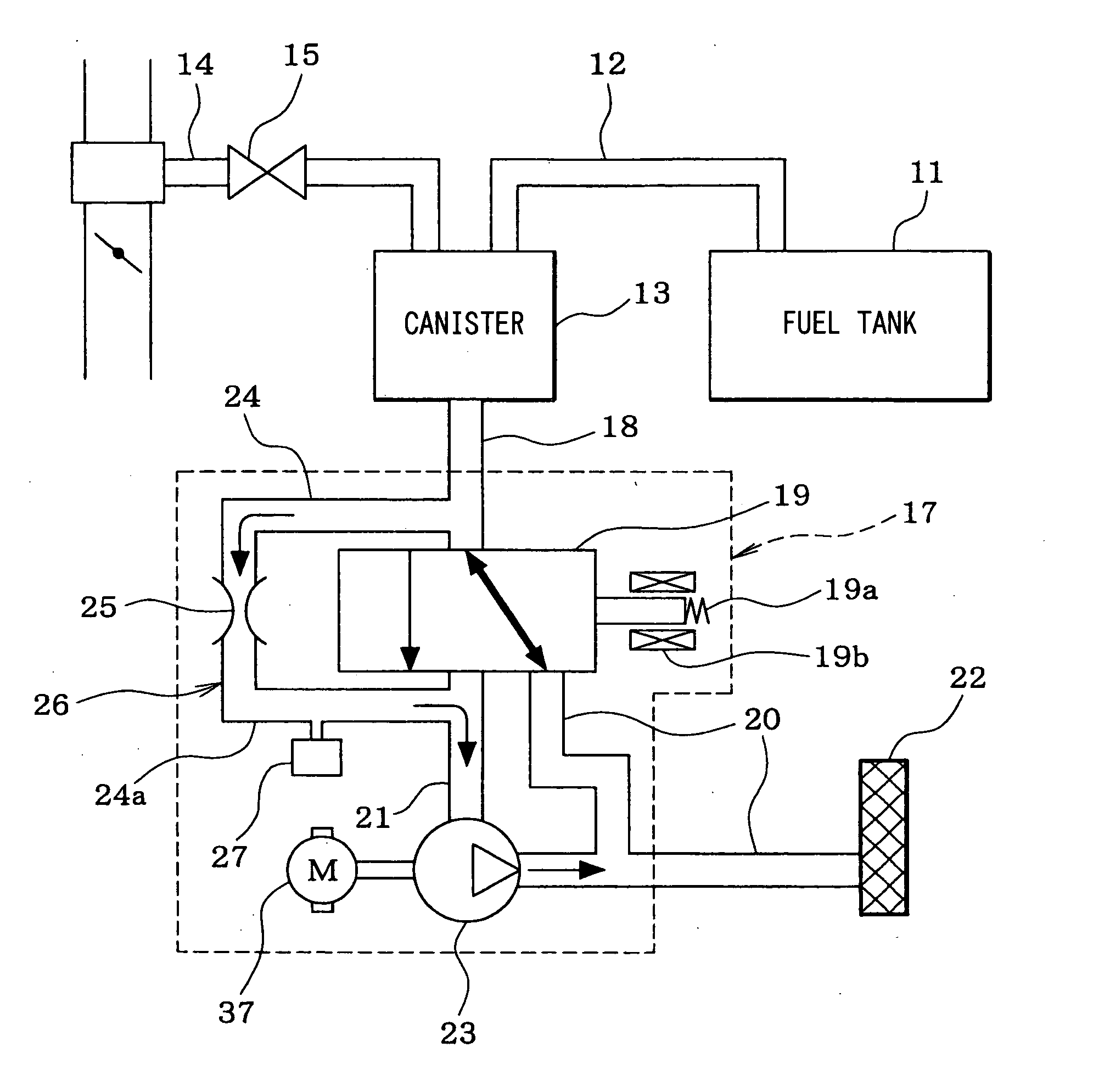
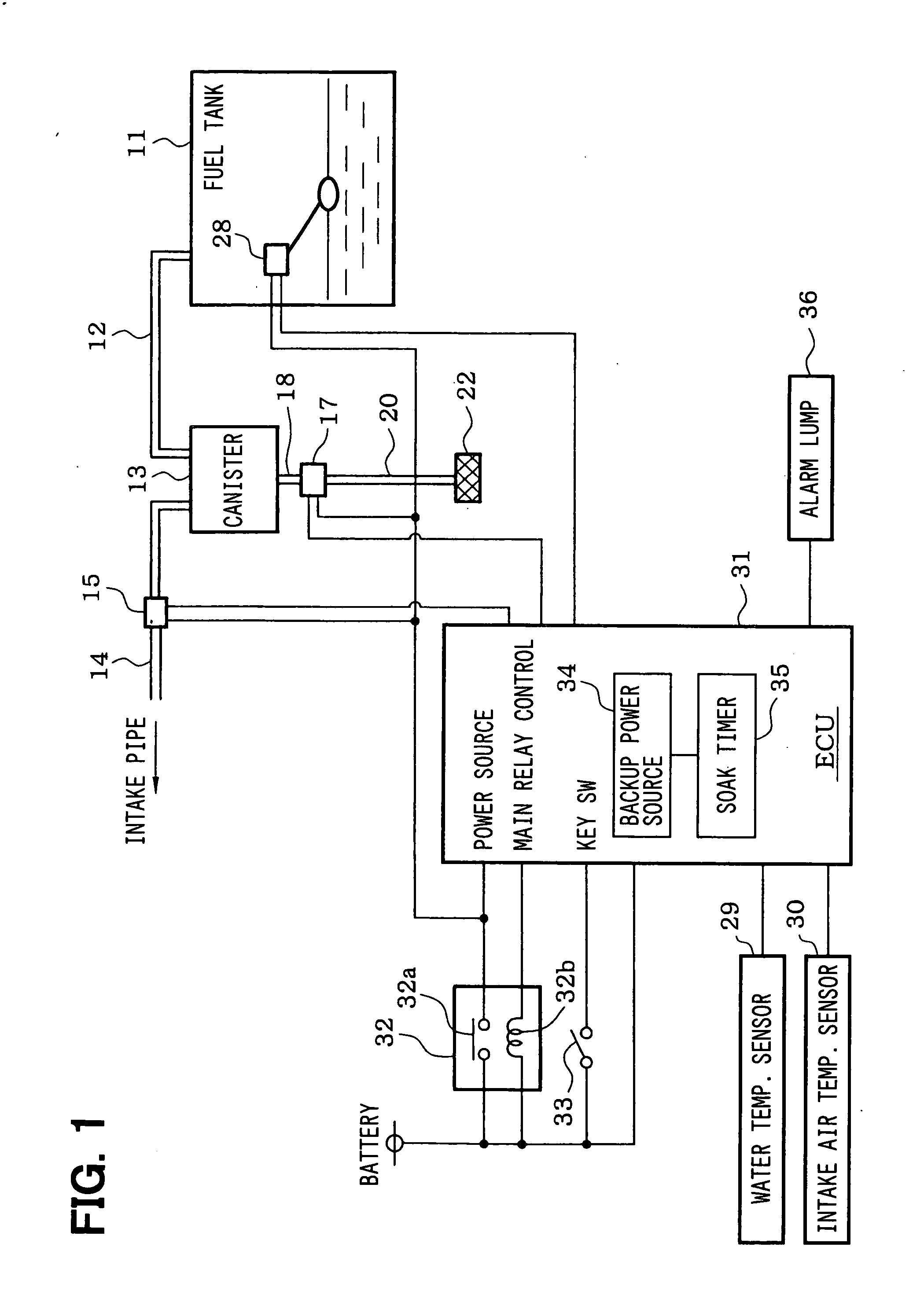
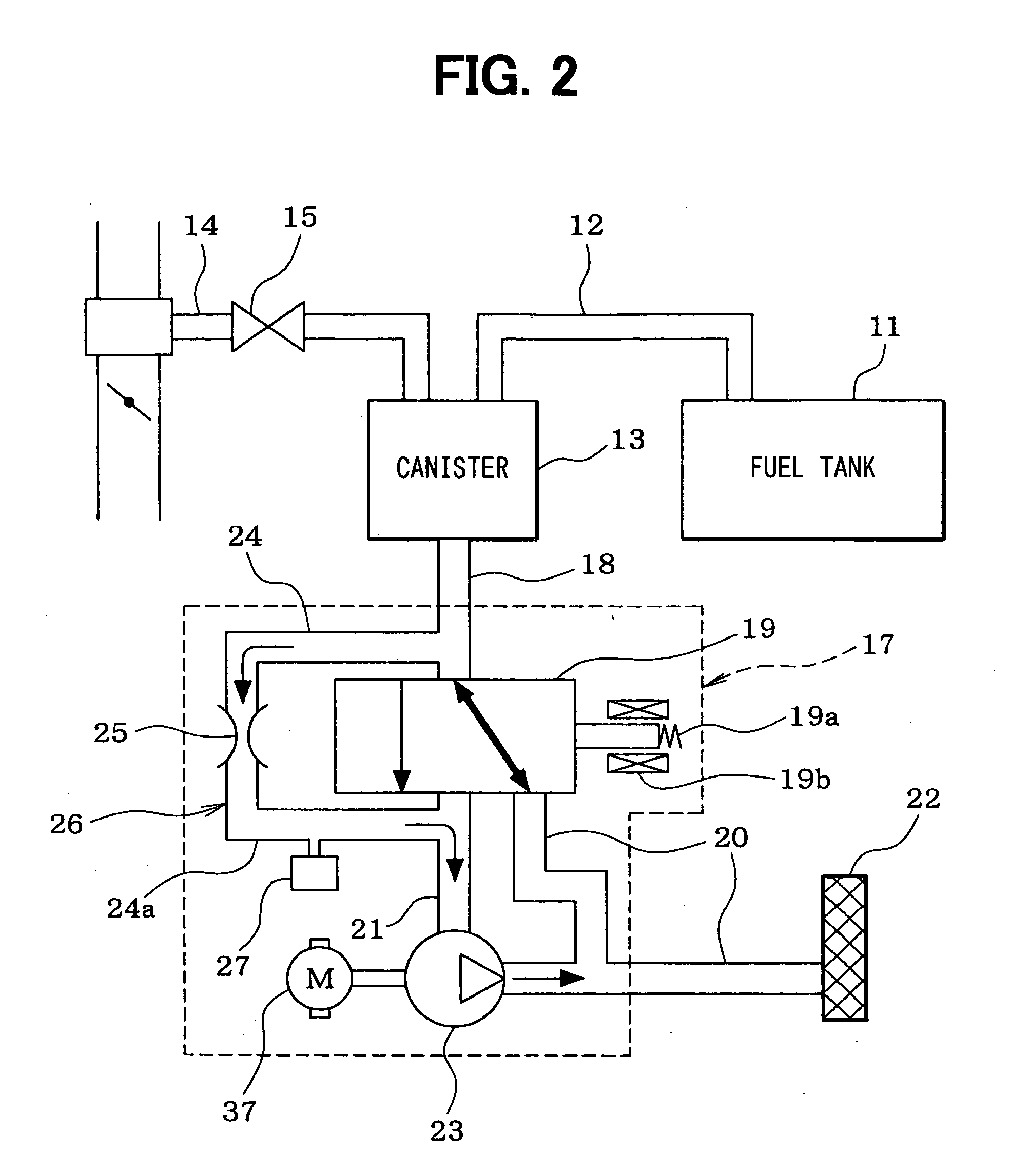
[0026] Referring to FIGS. 1 to 8, a first embodiment is described hereinafter.

[0027]FIG. 1 is a schematic view of a fuel vapor purge system. A canister 13 is connected to a fuel tank 11 through an evaporation passage 12. The canister 13 accommodates an absorber such as an activated carbon (not shown) which absorbs fuel vapor generated in the fuel tank 11.

[0028] A purge passage 14 connects the canister 13 with an intake pipe of the engine (not shown) in order to purge the absorbed fuel vapor from the canister 13 and introduce the purged fuel vapor into the intake pipe. The purge passage 14 has a purge-control valve 15 in order to control the amount of purged fuel vapor which is introduced into the intake pipe. The purge-control valve 15 is a normally closed valve driven by duty-control.

[0029] A leak check module 17 (pressure introduction detecting apparatus) is connected to the canister 13. As shown in FIGS. 2 and 3, the leak check module 17 has a canister-communicating passage 18...

second embodiment

[0074] Referring to FIGS. 9 to 12, a second embodiment will be described hereinafter.

[0075] In a case of detecting a leak hole which corresponds to a second aperture of which diameter (for example, 0.6 mm) is different from that of the reference orifice (for example, 0.5 mm), the reference pressure Pr is corrected according to the diameter of the second aperture. Comparing the corrected reference pressure Pr with the pressure Pf in the fuel vapor purge system, it can be determined whether a leak hole corresponding to the second aperture exists.

[0076] According to the second embodiment, as shown in FIG. 9, the first driving voltage V1 is corrected according to the diameter of the second aperture to obtain a second driving voltage V2. The suction pump 23 is driven at the driving voltage V2 when the pressure detecting process is conducted.

[0077] As shown in FIG. 10, after the suction pump 23 is driven at the first driving voltage V1 to detect the reference pressure Pr, the suction p...


PUM


Abstract

A suction pump introduces negative pressure into a reference-pressure-detecting portion. A driving voltage V of the suction pump is adjusted in such a manner that pressure Pr in the reference-pressure-detecting portion is within a target pressure range. When the pressure Pr is brought into the target pressure range, the driving voltage V of the suction pump is stored as a first driving voltage V1 and the pressure Pr is stored as a reference pressure Pr. When pressure detection and leak detection process are conducted, the suction pump is driven at the first driving voltage V1 to introduce the negative pressure. The computer compares the pressure Pr with a leak determination value to determine whether a leak exists.

Description

CROSS REFERENCE TO RELATED APPLICATIONS [0001] This application is based on Japanese Patent Application No. 2004-318645 filed on Nov. 2, 2004, the disclosure of which is incorporated herein by reference. FIELD OF THE INVENTION [0002] The present invention relates to a leak detector for fuel vapor purge system. The fuel vapor purge system introduces fuel vapor generated in a fuel tank into an intake pipe of the internal combustion engine. The leak detector determines whether leak exists in the fuel vapor purge system. BACKGROUND OF THE INVENTION [0003] The fuel vapor purge system includes a canister communicated to a fuel tank and a purge-control vale disposed between the canister and the intake pipe. The canister absorbs the fuel vapor which is generated in a fuel tank. When the purge-control valve is opened, the fuel vapor absorbed in the canister is introduced into the intake pipe by intake pressure which is negative pressure, so that the fuel vapor is prevented from leaking into ...

Claims


Application Information

Patent Timeline
IPC IPC(8): G01M19/00G01M99/00
CPCF02M25/0818F02M25/0836F02M25/0854F02M25/0872F02M25/089
Inventor NAGASAKI, KENJIITO, TOKIJIMIYAHARA, HIDEKI
Owner TOYOTA JIDOSHA KK
Learn More