
Tire wear sensor

a technology of tire wear and sensor, which is applied in vehicle tyre testing, instruments, roads, etc., can solve the problems of tire wear down the tread portion of the tire, tire treads that are limited in life, and tires that are no longer able to perform the intended functions, etc., to achieve simple construction and design, high reliability, and easy use.

Inactive Publication Date: 2006-05-04
RASKAS ERIC J
View PDF22 Cites 53 Cited by
  • Summary
  • Abstract
  • Description
  • Claims
  • Application Information

AI Technical Summary

Benefits of technology

[0011] Another object of the present invention is to provide a tire wear sensor that is of simple construction and design and which can be easily employed with highly reliable results.

Problems solved by technology

As the tires are used, they wear down the tread portion of the tire due to the frictional engagement of the tire to a road surface.
Tire treads have a limited life that is directly related to the number of miles traveled by the tire.
As the tread wears down the tire is no longer able to perform its intended functions.
When a tire tread is completely worn the driver may be at a greater risk of losing control of the vehicle due to the lack of appropriate friction and gripping power of the tread.
The tire may also rupture presenting a further risk to the driver and the tire fragments may cause risk to other drivers.
The rupture of the tire is also costly due to the loss of the casing and the inability to have the tire retread.
Further, tires, particularly for large vehicles or trucks, are expensive and it is important to monitor wear conditions to be able to change the tire prior to the tire failure.
These devices are only capable of monitoring tire pressure and are incapable of monitoring tread wear.
Further, these devices are easily damaged because they are outside the tire and are susceptible to collisions or weather.
However, one problem common to these known devices is that it is difficult to attach the devices to the inside surface of the tire.
In particular, tires are subject to numerous forces such as rotational forces and impact forces.
Another problem associated with attaching a monitoring device to an interior surface of the tire is that the weight of the device interferes with the balance of the tire.
A further problem of these devices is that they are not capable of monitoring the wear characteristics of a tire.
Also, the molded in wear indicator may be difficult to see to determine if the tire needs to be changed.

Method used


Image

  • Tire wear sensor
  • Tire wear sensor
  • Tire wear sensor

Examples


Embodiment Construction

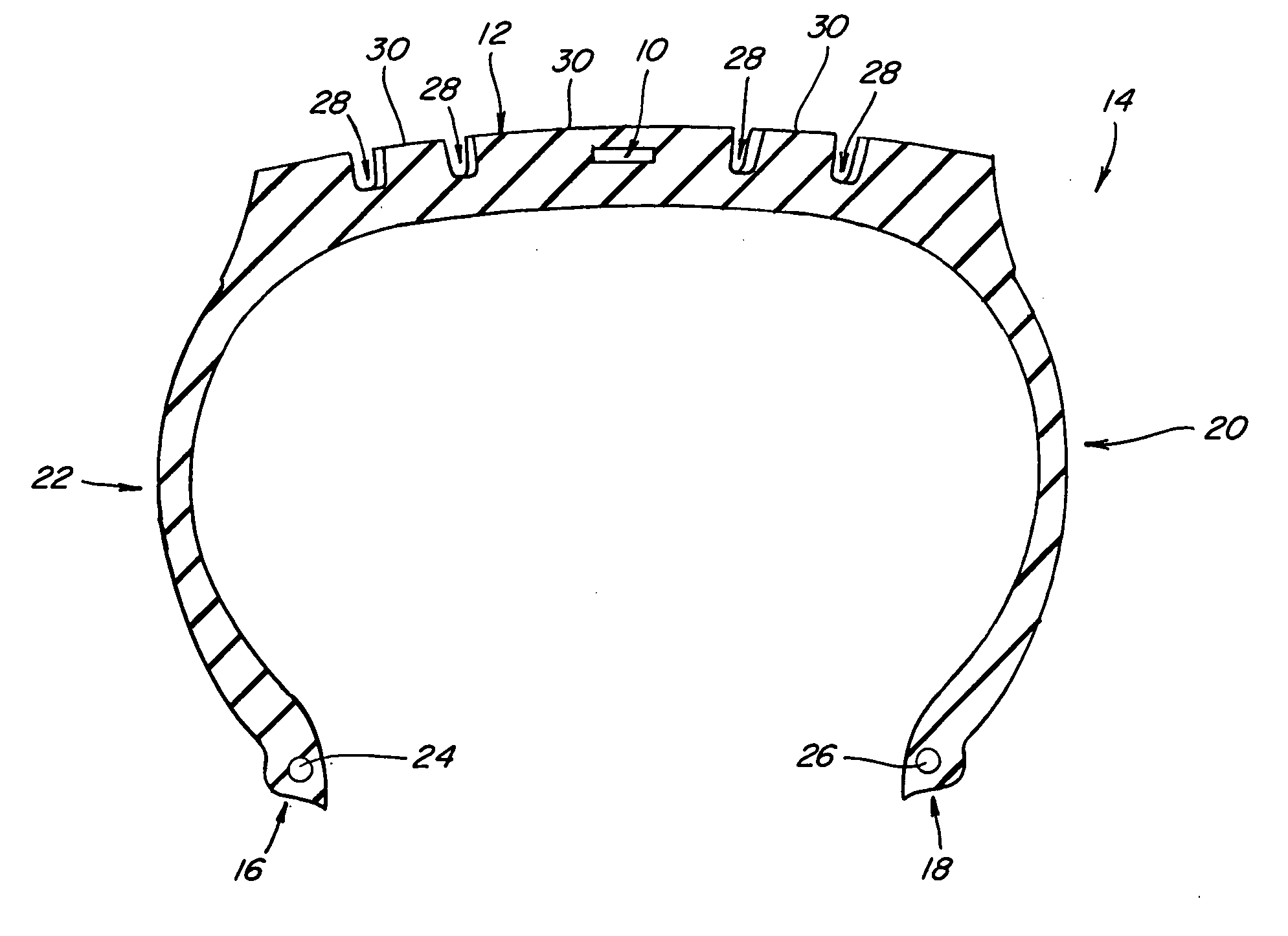
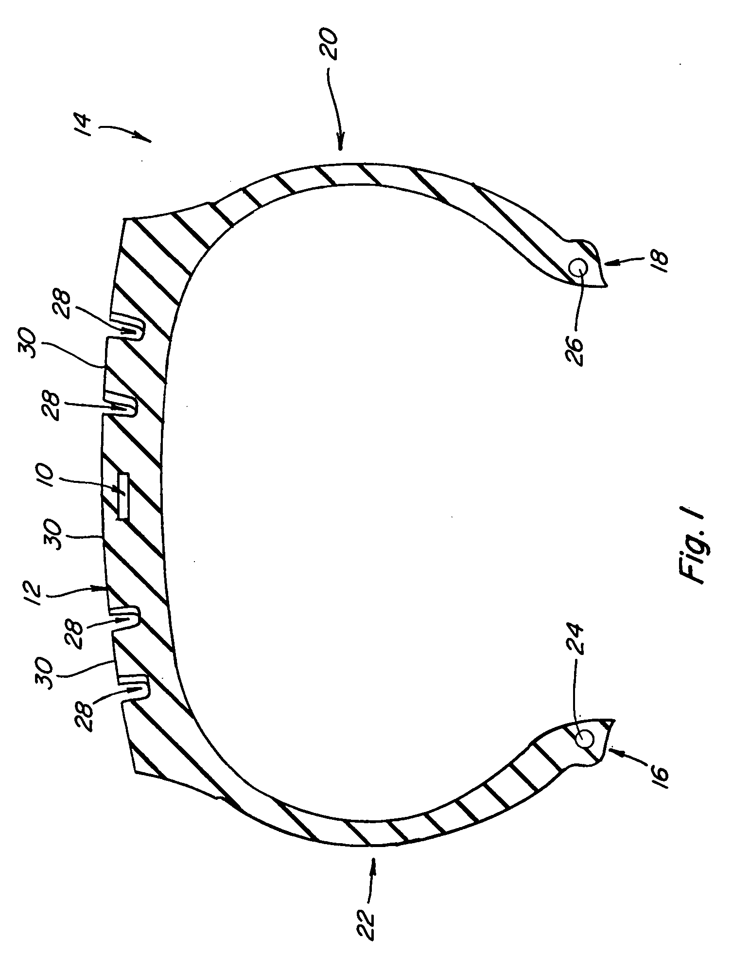
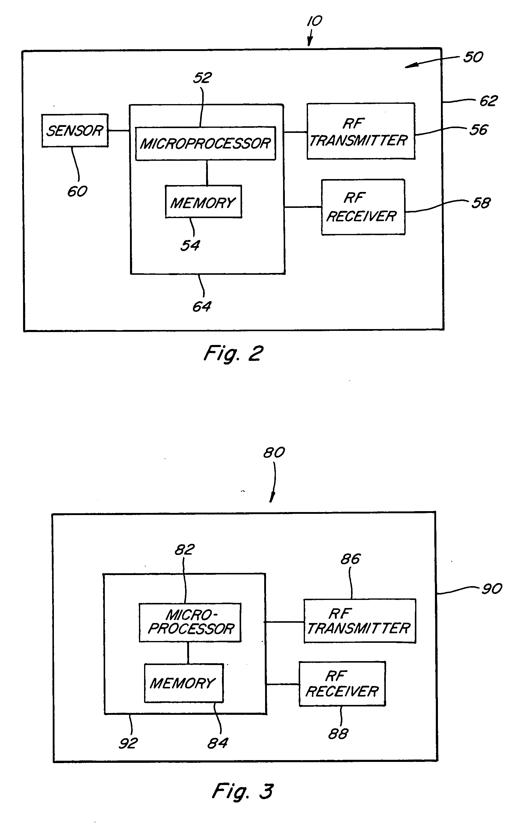
[0025] Referring now to the drawings, wherein like numbers refer to like items, number 10 identifies a preferred embodiment of a tire wear sensor constructed according to the present invention. With particular reference to FIG. 1, the tire wear sensor 10 is shown embedded within a tread portion 12 of a tire 14. The tire 14 is shown in cross-section having a pair of bead portions 16 and 18, a pair of sidewall portions 20 and 22, and the tread portion 12 toroidally extending between the sidewall portions 20 and 22. The tire 14 may also include a bead core 24 embedded in the bead portion 16 and a bead core 26 embedded in the bead portion 18. Although not shown, the tire 14 may further include other components such as a belt or belts, belt plies, plies, cords, and an air impermeable liner. The tread portion 12 may include grooves 28 and ribs 30. The grooves 28 and the ribs 30 may take on any known tread pattern or tread design. The tire wear sensor 10 is molded in place in the tread por...


PUM


Abstract

A tire wear sensor for monitoring wear of a tire comprises a sensor mounted within a tread of a tire, the sensor for monitoring wear of a tire and for generating a signal indicative of a tire needing replacement and a controller for receiving the signal.

Description

BACKGROUND OF THE INVENTION [0001] This invention relates generally to a tire wear sensor for a tire, and more particularly, to a tire wear sensor for monitoring the wear characteristics of the tread portion of a tire. [0002] Wheeled vehicles have tires, such as pneumatic tires, mounted on wheels. As the tires are used, they wear down the tread portion of the tire due to the frictional engagement of the tire to a road surface. Tire treads have a limited life that is directly related to the number of miles traveled by the tire. As the tread wears down the tire is no longer able to perform its intended functions. When a tire tread is completely worn the driver may be at a greater risk of losing control of the vehicle due to the lack of appropriate friction and gripping power of the tread. The tire may also rupture presenting a further risk to the driver and the tire fragments may cause risk to other drivers. The rupture of the tire is also costly due to the loss of the casing and the ...

Claims


Application Information

Patent Timeline
IPC IPC(8): G01M17/02
CPCB60C11/24B60C19/00
Inventor RASKAS, ERIC J.
Owner RASKAS ERIC J
Learn More