Multi-channel cross-flow porous device

a porous device and cross-flow technology, applied in the field of membrane modules, can solve the problems of the fragility of known single or bundled ceramic hollow fibers to be practical, and the inability to withstand organic solvents

Inactive Publication Date: 2006-05-04
CORNING INC
View PDF30 Cites 82 Cited by
  • Summary
  • Abstract
  • Description
  • Claims
  • Application Information

AI Technical Summary

Problems solved by technology

However, known single or bundled ceramic hollow-fibers are too fragile to be of practical use.
However, the main problems with polymer materials are their susceptibility to attack by organic solvents and their instability at high temperatures (e.g. >250° C.) and other harsh operating environments.
The porous polymeric support is not suitable for supporting inorganic membrane materials.
However, inorganic zeolites can not be applied to the incompatible organic polymeric material.
However, the ceramic hollow fibers could not be made with the required mechanical strength and flexibility in an economical way.
The hollow-fiber ceramic tubes have a high surface area but are fairly brittle.
The inorganic membranes have poor mechanical flexibility, low membrane surface area per unit module volume, difficulty in membrane processing and module assembly, and high capital costs.
However, the key problem is how to manage the flow into or out of the embedded membrane channels or tubes, when there is no open or free space available between the embedded tubes.
However, the disk-shaped or single-channel tubular inorganic membrane module has a low separation surface area per unit volume.
Such a monolithic design presents a challenge in how to introduce the sweep flow stream for an efficient removal of the adsorbed or permeated species.
As a result, only the outside of the module surface is “purged”, while the permeate from the inner channels could not be reached.
The challenge is how to conduct the purge of a membrane module with a number of flow channels being embedded in a solid but porous matrix.
How to purge every membrane channels in a monolith membrane support is the challenge.

Method used


Image

  • Multi-channel cross-flow porous device
  • Multi-channel cross-flow porous device
  • Multi-channel cross-flow porous device

Examples


Embodiment Construction

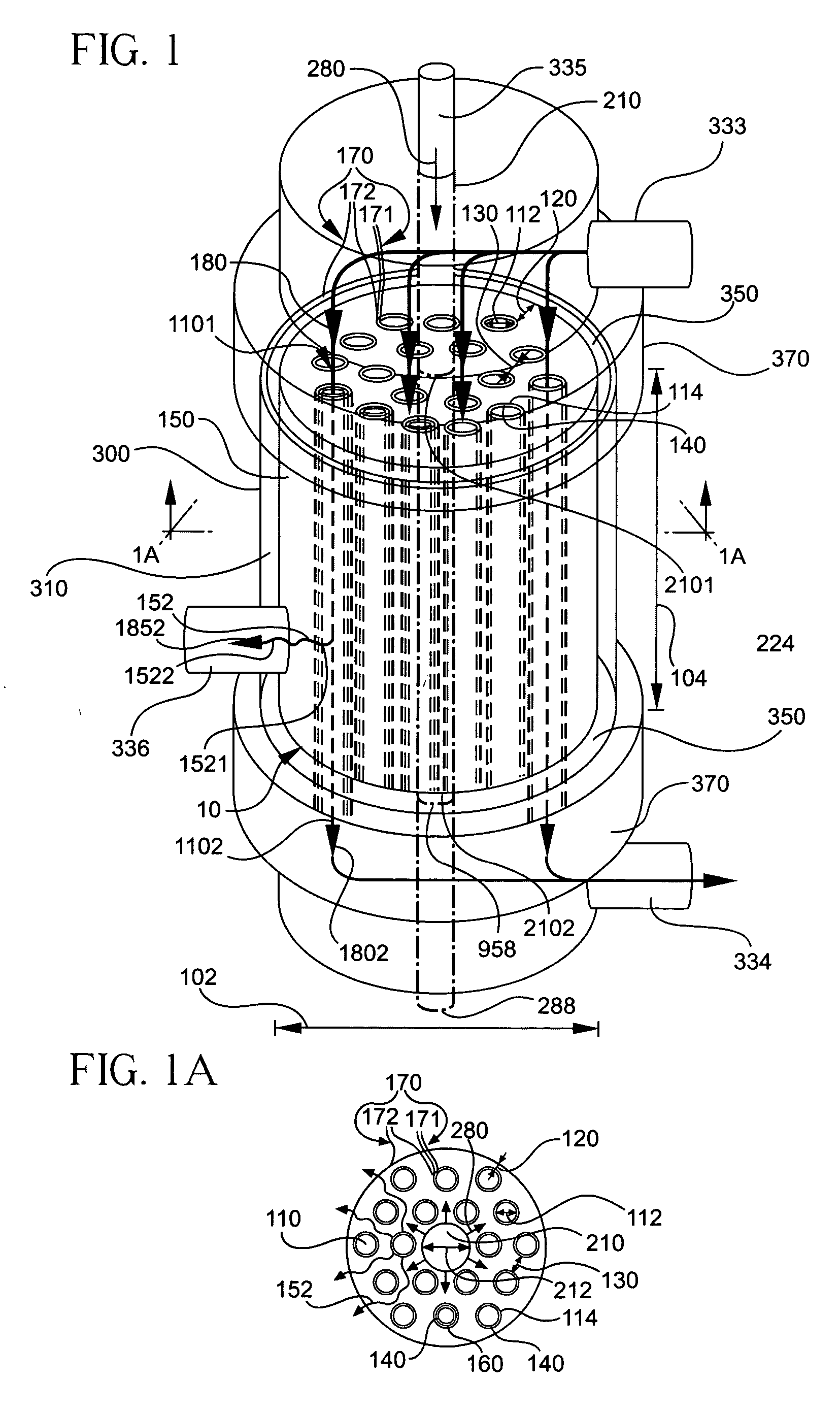
[0041] Reference will now be made in detail to the present preferred embodiments of the invention, examples of which are illustrated in the accompanying drawings. Whenever possible, the same or similar reference numerals will be used throughout the drawings to refer to the same or like parts. Even when not numbered in the drawing but referenced in the text, the same or similar parts or dimensions can always be seen in FIG. 1 or FIG. 1A. Note however that the drawings are not necessarily drawn to scale and not all flow arrows are shown for simplicity. One embodiment of the multi-channel modular device 10 for processing between two fluid streams of different compositions of the present invention is shown in FIG. 1, and is designated generally throughout by the reference numeral 10. The processing can be mass transfer or exchange between any two fluid streams, where the two fluid streams are a raw feed stream and a sweep stream, or any other two different fluid streams. In general, the...


PUM

PropertyMeasurementUnit
pore sizeaaaaaaaaaa
porosityaaaaaaaaaa
hydraulic diameteraaaaaaaaaa

Abstract

A multi-channel modular device (10) processes between two fluid streams of different compositions. The device (10) includes a porous body (150) having a first plurality of feed-flow pathways (110) disposed in the body (150) for transporting a first stream (180). A pathway wall (114) surrounds each of the first plurality of feed-flow pathways (110) for processing the first stream (180) into a first composition (1852) and a second composition (1802). At least one feed-flow inlet (1101) is disposed in the body (150) for introducing the first stream (180) into the first plurality of feed-flow pathways (110). At least one feed-flow outlet (1102) is disposed in the body (150) for discharging the remaining first stream containing the second composition (1802). At least one second pathway (210) is disposed in the body (150) for transporting a second stream (280) having a second inlet (2101) and a second outlet (2102). A networked plurality of fluid conduits (152) formed in the porous body (150) provides the flow-conduit for the second stream (280) to sweep the first composition (1852) from each of the first plurality of the feed-flow pathways (110) to the second outlet (2102). A vessel (300) ports the inlets (1101 and 2101) and outlets (1102 and 2102) to provide a second stream flow access and for spacing the body within and away from the inner surfaces of the vessel (300) to provide a gap (310) for access. A partition (350) is disposed in the gap between the body and the vessel for diverting the flow within the gap (310).

Description

CROSS-REFERENCE TO RELATED APPLICATIONS [0001] This is a continuation-in-part of U.S. Patent Application Serial No. U.S. parent application Ser. No. 10 / 978,126 filed on U.S. Parent Application Filing Date Oct. 29, 2004, the content of which is relied upon and incorporated herein by reference in its entirety, and the benefit of priority under 35 U.S.C. § 120 is hereby claimed.BACKGROUND OF THE INVENTION [0002] 1. Field of the invention [0003] The present invention relates generally to processing between two fluid streams of different compositions, and particularly to a membrane module for separation, purification, mass transport, exchange, or other types of processing applications of process streams involving the use of a purging, sweep or any other type of a second fluid stream. [0004] 2. Technical Background [0005] Cross-flow filtration is known where the permeate flow conduits are disposed perpendicular or transverse to the feed flow conduits. Purge flow to sweep the permeate flow...

Claims


Application Information

Patent Timeline
Patent Type & Authority Applications(United States)
IPC IPC(8): B01D53/02
CPCB01D46/0036B01D46/2407B01D46/543B01D53/22B01D53/229B01D63/022B01D63/066B01D71/02B01D71/022B01D71/028B01D2253/108B01D2256/16B01D2257/702B01D2257/80B01D2311/13B01D2313/42B01D2315/10B01J12/007B01J19/2475B01J19/2485C01B3/38C01B3/503C01B3/505C01B3/56C01B2203/0233C01B2203/0244C01B2203/0261C01B2203/0405C01B2203/041C01B2203/0465C01B2203/047C01B2203/0475C01B2203/048C01B2203/0495C04B38/0003C04B38/0074C04B2111/00793C04B2111/0081B01D46/60C04B35/00C04B38/0054C04B35/185
Inventor LIU, WEIWILLIAMS, JIMMIEXIE, YUMING
Owner CORNING INC
Why Eureka
Try Eureka