

Self-sealing electrical cable using rubber resins
a technology of electrical cables and resins, which is applied in the direction of cables, insulated conductors/cables, insulation conductors, etc., can solve the problems of affecting the sealing effect of electrical cables, the inability of cables to stand up to the rigors of handling, installation and operation, and the deterioration of exposed aluminum. , to achieve the effect of preventing moisture migration
- Summary
- Abstract
- Description
- Claims
- Application Information
AI Technical Summary
Benefits of technology
Problems solved by technology
Method used
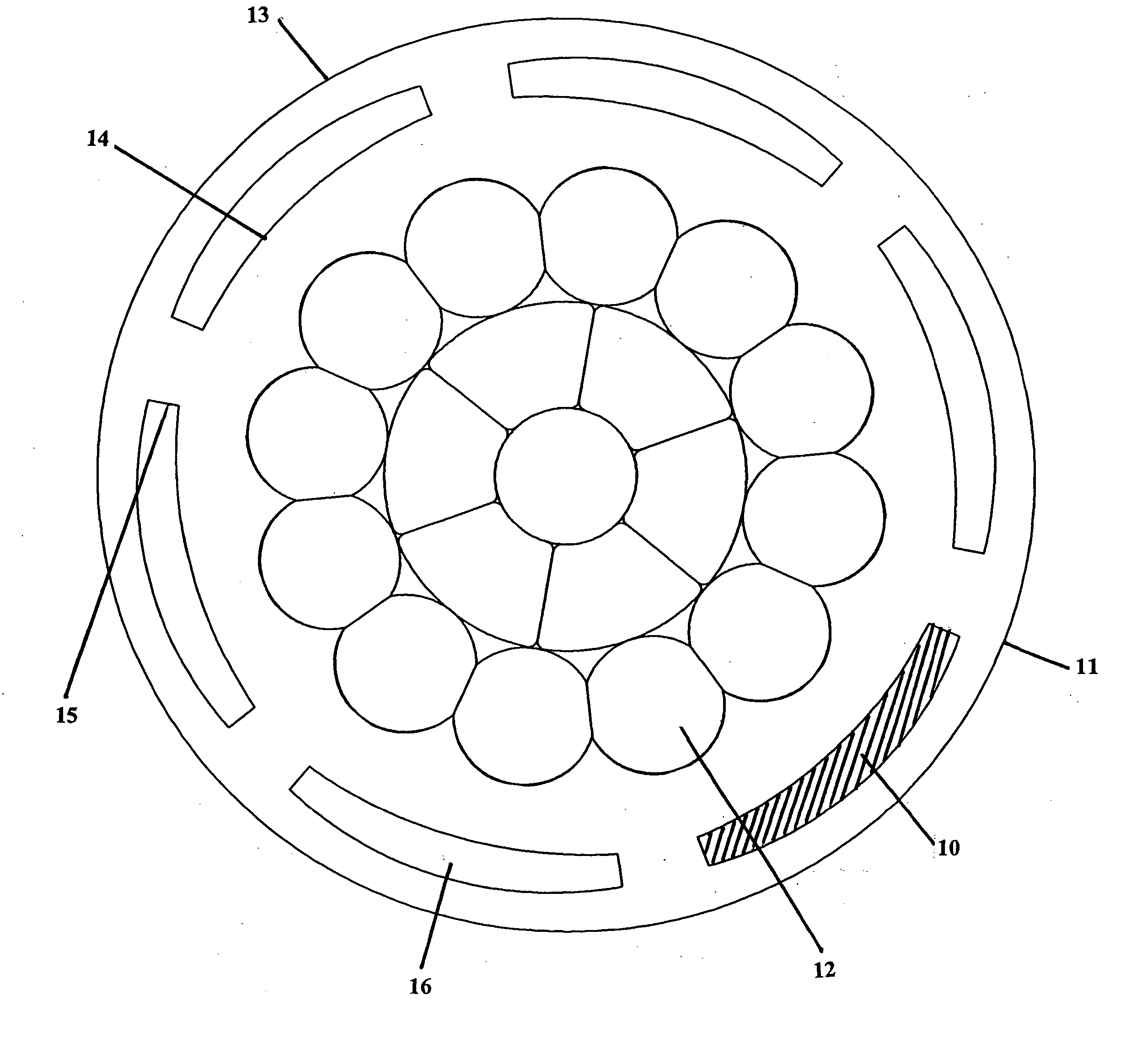
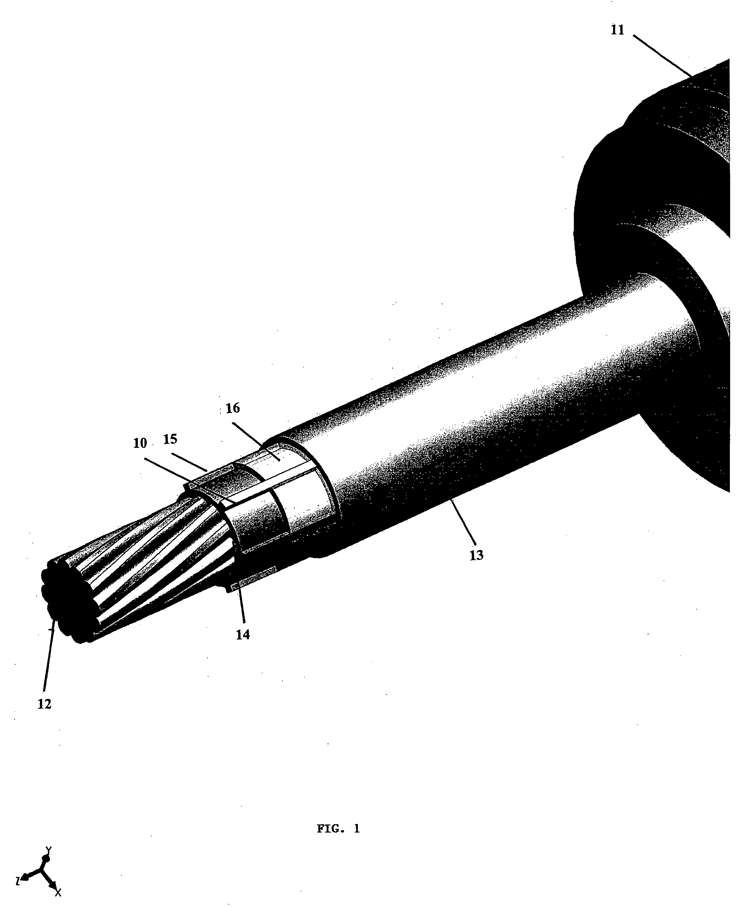
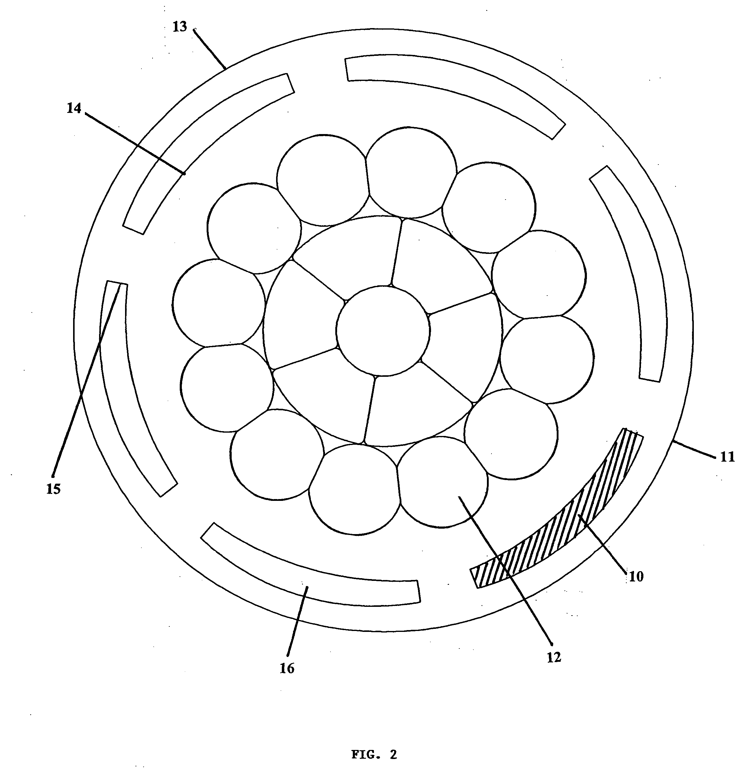
Image

Examples
example 1
[0073] This test was designed to evaluate the performance of the present invention's self sealing, 600 V underground cable. The test program was patterned after a previously developed procedure to evaluate self-sealing or self-repairing cable designs.
[0074] To conduct the test damaged cables were placed in a specially mixed, moist soil. The cables were then energized with 120 V ac to ground. Measurements made included changes in leakage current to earth and cable conductor resistance. The temperature of each cable near the damage point was also monitored.
[0075] Four control sample replicates and eight self-sealing sample replicates were evaluated. All four control samples failed the test relatively early in the test program. All eight self-sealing samples performed well, with no significant increase in conductor resistance and low leakage current values throughout the 60-day test period.
[0076] Conventional and self-sealing 600 volt underground cable with a 2 / 0 AWG combination uni...
PUM
| Property | Measurement | Unit |
|---|---|---|
| density | aaaaa | aaaaa |
| thickness | aaaaa | aaaaa |
| impulse breakdown | aaaaa | aaaaa |
Abstract
Description
Claims
Application Information