Sedimentation removal assembly for flow-through sedimentary tank
- Summary
- Abstract
- Description
- Claims
- Application Information
AI Technical Summary
Benefits of technology
Problems solved by technology
Method used
Image
Examples
Embodiment Construction
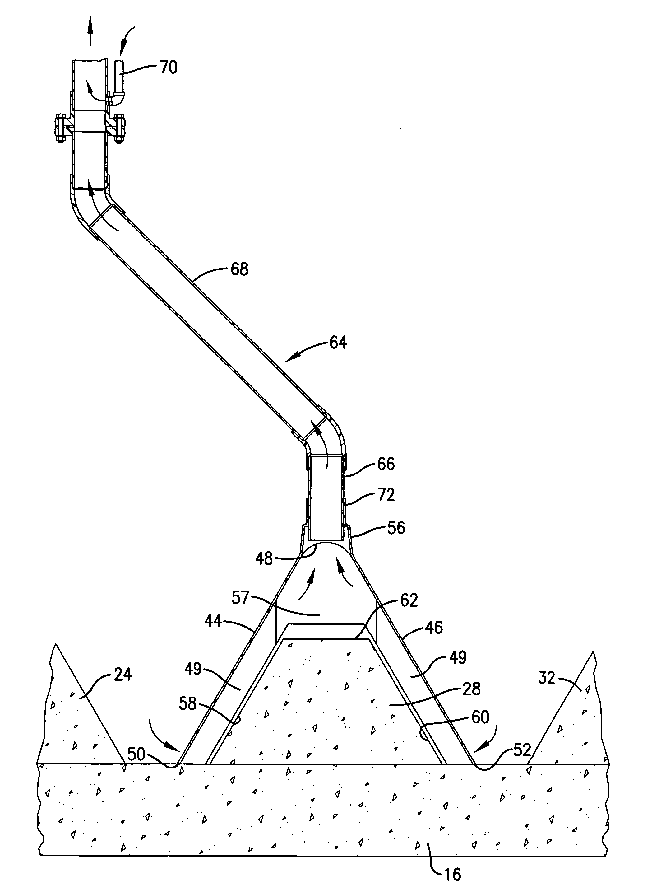
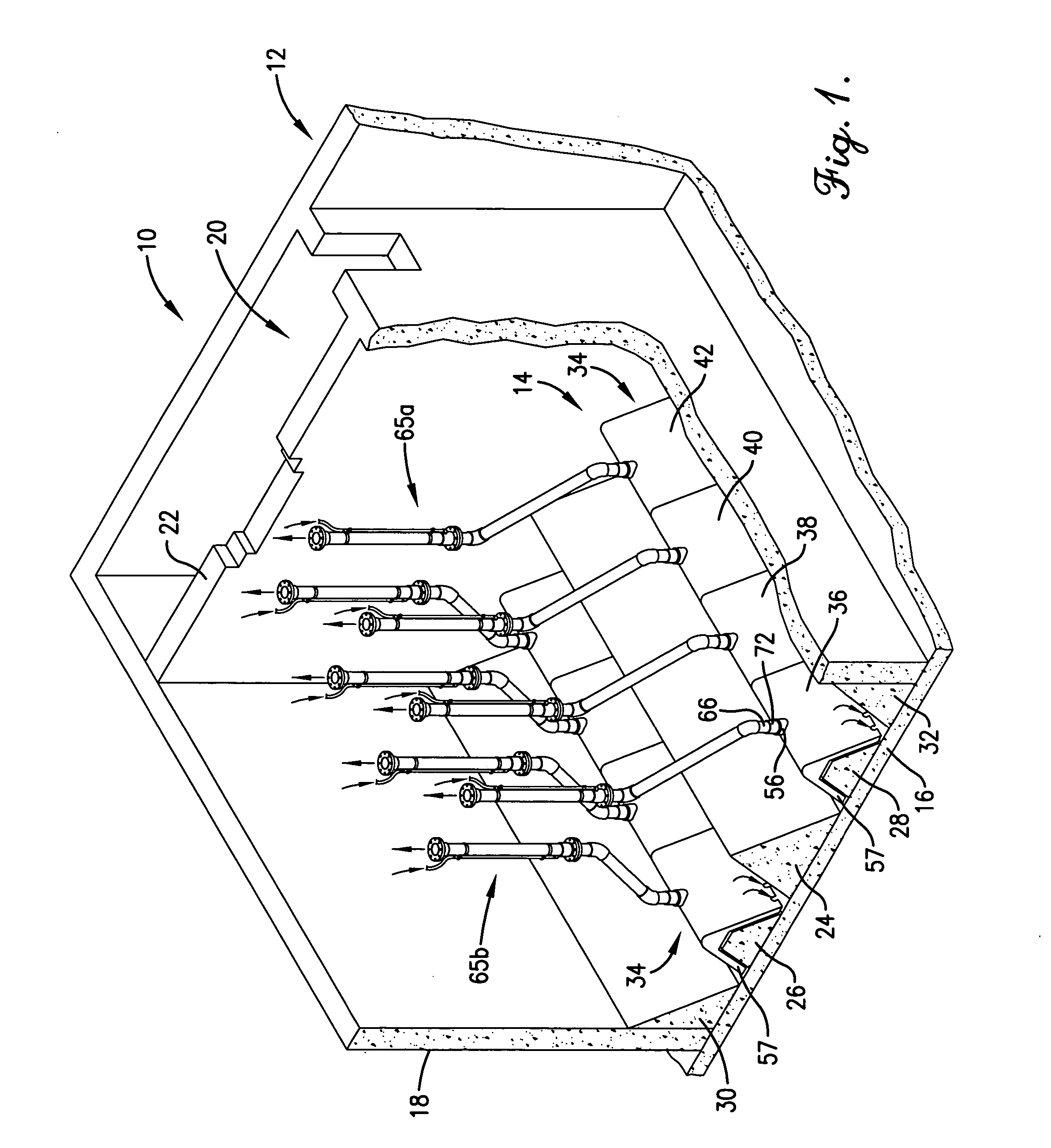
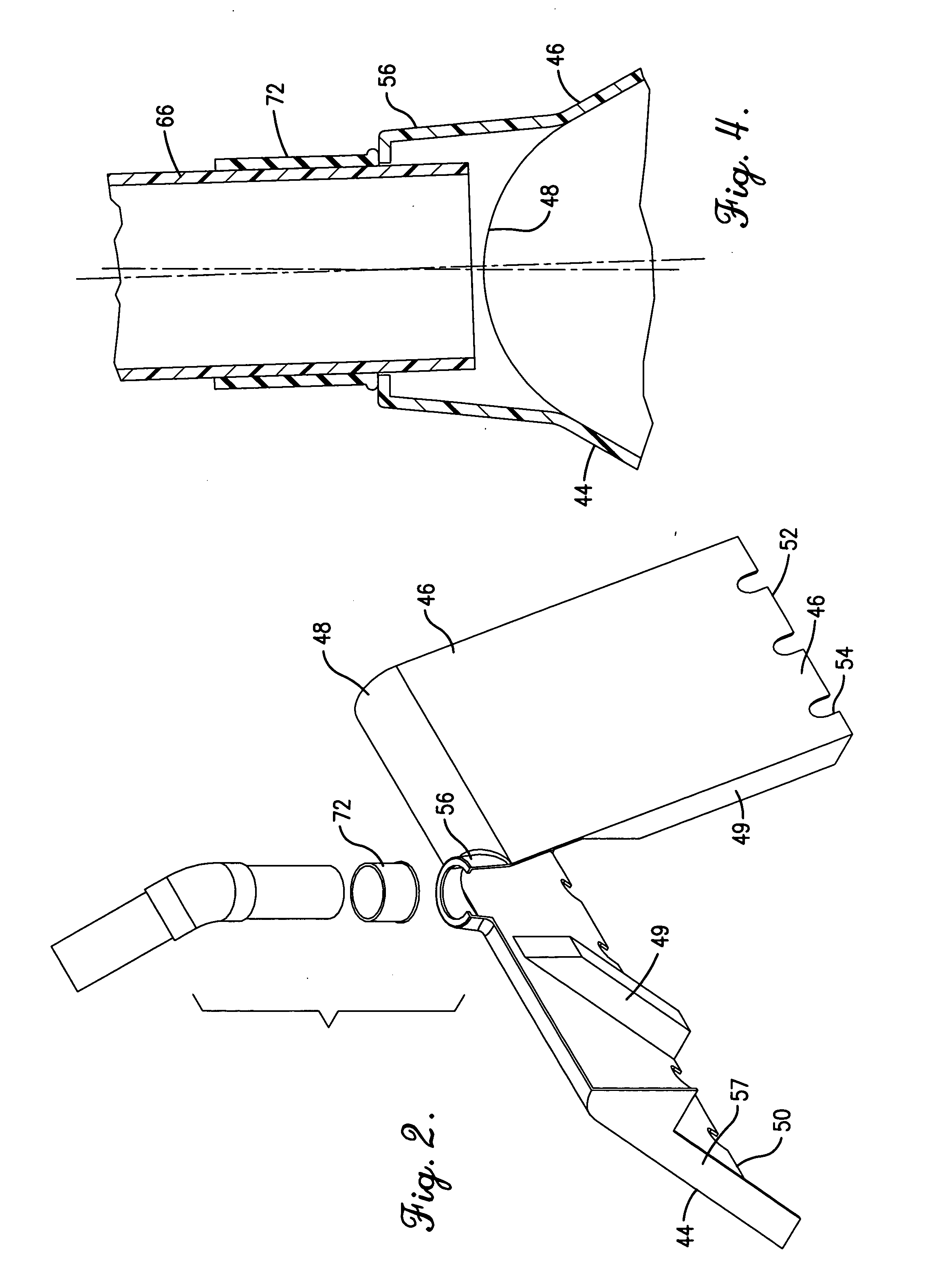
[0017] Turning now to the drawings, FIG. 1 illustrates a sedimentation tank assembly 10 broadly including an upright sedimentation tank 12 as well as a plurality (here two) of sedimentation removal assemblies 14 located adjacent the bottom of the tank 12. The assembly 10 is designed to efficiently remove solids of various densities from incoming waste water as a part of treatment thereof. The overall assembly 10 is similar in many respects with the clarifier assembly described in U.S. Pat. No. 5,035,795incorporated by reference herein, particularly in the details of construction relating to waste water inlets and outlets. That is, the present invention is particularly directed to the improved, below water level assemblies 14, and these may be employed in a variety of different types of sedimentation or other solids removal tank systems.
[0018] In more detail, the tank 12 is formed of poured concrete and includes a bottom wall 16 as well as upstanding tank-defining sidewalls 18. The ...
PUM
| Property | Measurement | Unit |
|---|---|---|
| Fraction | aaaaa | aaaaa |
| Angle | aaaaa | aaaaa |
| Angle | aaaaa | aaaaa |
Abstract
Description
Claims
Application Information
 - R&D
- Intellectual Property
- Life Sciences
- Materials
- Tech Scout
- Unparalleled Data Quality
- Higher Quality Content
- 60% Fewer Hallucinations
Browse by: Latest US Patents, China's latest patents, Technical Efficacy Thesaurus, Application Domain, Technology Topic, Popular Technical Reports.
© 2025 PatSnap. All rights reserved.Legal|Privacy policy|Modern Slavery Act Transparency Statement|Sitemap|About US| Contact US: help@patsnap.com


