LED module and method of packaging the same

Inactive Publication Date: 2006-05-04
LEXTAR ELECTRONICS CORP
View PDF4 Cites 13 Cited by
  • Summary
  • Abstract
  • Description
  • Claims
  • Application Information

AI Technical Summary

Benefits of technology

[0015] It is therefore an objective of the present invention to provide an LED module and method of packaging the same for reducing the volume of the LED module and being applicable to high power LED modules.
[0016] It is another objective of the

Problems solved by technology

Essentially, a defective LED chip or a poor wire bonding process will result in a nonfunctional LED module, which will also affect the overall reliability and cost of the final product.
Hence, as the capsulation material layer 14 gets more rigid, the stress level of the overall package structure will increase accordingly, which will easily cause the capsulation material layer 14 to break in half or detach from the substrate 10 and decrease the reliability of the product.
In addition to the fact that the volume of the single LED package body 36 is significantly larger than the conventional mult

Method used


Image

  • LED module and method of packaging the same
  • LED module and method of packaging the same
  • LED module and method of packaging the same

Examples


Embodiment Construction

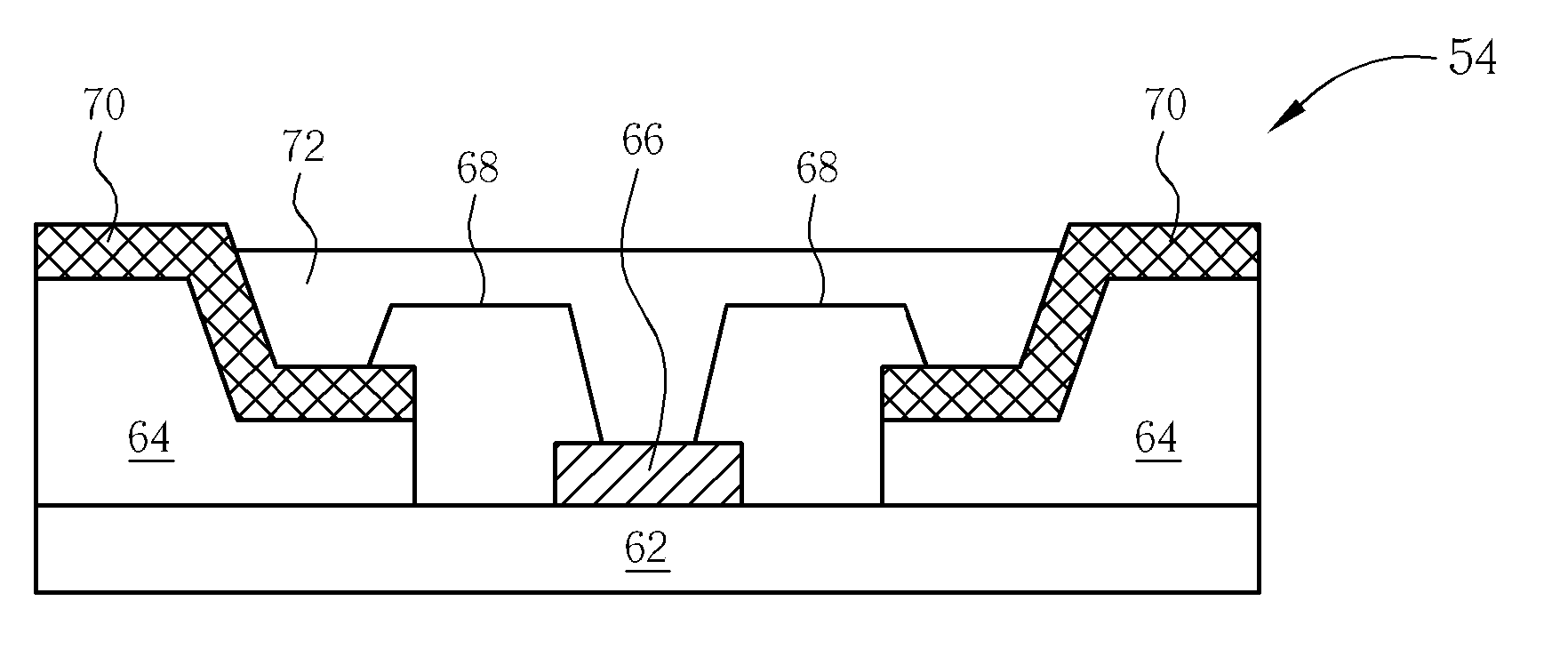
[0022] Please refer to FIG. 3. FIG. 3 is a perspective diagram showing the package of an LED module according to the present invention. As shown in FIG. 3, an LED module includes a substrate 50, in which the substrate 50 includes at least one cavity 52, at least one LED unit 54 positioned on portions of the substrate 50 in the cavity 52, a circuit 58 soldered to a solder pad 56 above the LED unit 54 and electrically connected to the LED unit 54, and a capsulation material layer 60 filled within the cavity 52.

[0023] According to the preferred embodiment of the present invention, the substrate 50 is a radiating substrate, such that one side of the substrate 50 is used for containing the cavity 52 of the LED unit 54, whereas the other side of the substrate 50 without the cavity 52 is used for forming radiating devices including radiating fins, radiating pipes, or active cooling devices. Alternatively, a radiating gel can also be used to fix the substrate 50 to a radiating device. The ...


PUM


Abstract

An LED module and method of packing the same are provided. The LED module includes a substrate with at least one cavity therein, at least one LED unit positioned on portions of the substrate in the cavity, a circuit positioned above the LED unit and electrically connected to the LED unit, and a first capsulation material filling within the cavity.

Description

BACKGROUND OF INVENTION [0001] 1. Field of the Invention [0002] The present invention relates to a light emitting diode (LED) module and method of packaging the same, and more particularly, to a high power LED module and method for packaging the same. [0003] 2. Description of the Prior Art [0004] In recent years, a new application field of high illumination light emitting diodes (LEDs) has been developed. Different from a common incandescent light, a cold illumination LED has the advantages of low power consumption, long device lifetime, no idling time, and quick response speed. In addition, since the LED also has the advantages of small size, vibration resistance, suitability for mass production, and ease of fabrication as a tiny device or an array device, it has been widely applied in display apparatus and indicating lamps used in information, communication, and consumer electronic products. The LEDs are not only utilized in outdoor traffic signal lamps or various outdoor displays...

Claims


Application Information

Patent Timeline
IPC IPC(8): H01L33/00H01L29/06H01L23/02H01L31/12H01L29/22H01L33/48H01L33/64
CPCH01L33/486H01L33/641H01L33/642H01L2224/48095H01L2224/48247H01L2924/181H01L2924/00012
Inventor CHANG, CHIH-CHINHUANG, TENG-HUEILEE, CHIEN-LUNG
Owner LEXTAR ELECTRONICS CORP
Why Eureka
Try Eureka