LC tank clock driver with automatic tuning

Active Publication Date: 2006-05-04
ANALOG DEVICES INC
View PDF4 Cites 7 Cited by
  • Summary
  • Abstract
  • Description
  • Claims
  • Application Information

AI Technical Summary

Benefits of technology

[0008] The present invention provides for a resonant LC clock driver (used in conjunction with a phase detector that is part of a clock and data recovery circuit) comprising a capacitance due to latches and interconnects, and an inductor as the resonant LC clock driver's load in parallel with the capacitance, wherein the inductor resonates out the capacitance due to latches and interconnects. A lower power consumption (than a purely resistive load) is achieved using the LC clock driver of the present invention.
[0009] In an extended embodimen

Problems solved by technology

A disadvantage with such an implementation is that the aggregate

Method used


Image

  • LC tank clock driver with automatic tuning
  • LC tank clock driver with automatic tuning
  • LC tank clock driver with automatic tuning

Examples


Example

[0026] Although the present invention has been shown and described with respect to several preferred embodiments thereof, various changes, omissions and additions to the form and detail thereof, may be made therein, without departing from the spirit and scope of the invention.

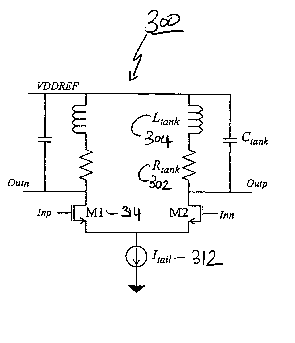
[0027] The present invention provides for a novel clock driver for use in the phase detector of a clock and data recovery circuit. The clock driver employs an inductor in its load to resonate out the capacitance presented by the clock lines in the phase detector. A programmable capacitance adjusts the center frequency of the tank so it matches the frequency of the clock. A finite state machine at startup determines the value of this programmable capacitance. A criterion for tuning the center frequency of the tank is to choose the capacitance which leads to the lowest power consumption.

[0028]FIG. 3a illustrates a LC tank-based clock driver 300. The quality factor of the tank, which is preferably in the range o...


PUM


Abstract

A new clock driver is described for the use in the phase detector of a clock and data recovery circuit (CDR). By building a resonant LC tank, whose center frequency is similar to the clock frequency, a low power clock driver is realized. A method based upon minimizing power consumption is described for determining the value of the programmable capacitance. A programmable capacitance adjusts the center frequency of the tank so it matches the frequency of the clock and a finite state machine at startup determines the value of this programmable capacitance. A criterion for tuning the center frequency of the tank is to choose the capacitance which leads to the lowest power consumption. A low Q tank affords a reasonable compromise between power efficiency and performance in the CDR circuit.

Description

BACKGROUND OF THE INVENTION [0001] The invention relates to the field of clock and data recovery circuit, and in particular to a LC tank clock driver with automatic tuning. [0002] One of the core blocks in a clock and data recovery circuit is the phase detector. A particular implementation of a phase detector is a half-rate binary phase detector reported by Hauenschild et al., in the paper entitled “A plastic packaged 10 GBPS and data recovery 1:4 demultiplexer with external VCO,” disclose a half-rate implementation that uses two clocks which are orthogonal to each other, wherein each clock is loaded by ten latches. A disadvantage with such an implementation is that the aggregate device and interconnect capacitance on the clocks are substantial. [0003] In high-speed applications, which often have tight jitter specifications, static CMOS logic is rejected in favor of current-mode logic (CML). FIG. 1 illustrates an example of a CML latch 100. A differential clock signal drives the low...

Claims


Application Information

Patent Timeline
IPC IPC(8): H03B5/08
CPCH03B2201/0266H03B5/1225H03B5/1228H03B5/1215H03B5/1209H03B5/1265H03B5/124
Inventor KENNEY, JOHN G. JR.REDDY, VISWABHARATHTITUS, WARD STEVEN
Owner ANALOG DEVICES INC
Why Eureka
Try Eureka