Liquid crystal display device

a liquid crystal display and display device technology, applied in non-linear optics, instruments, optics, etc., can solve the problems of oblique presence, inversion direction of image tone when inverted, deterioration of image quality, etc., to reduce the difference in layer thickness, eliminate such difference, and improve image quality

Inactive Publication Date: 2006-05-04
HITACHI DISPLAYS
View PDF9 Cites 76 Cited by
  • Summary
  • Abstract
  • Description
  • Claims
  • Application Information

AI Technical Summary

Benefits of technology

[0010] Here, all of Japanese Patent Laid-Open Hei9(1997)-329813 (patent document 1), Japanese Patent Laid-Open 2002-98961 (patent document 2)and Japanese Patent Laid-Open 2002-48917 (patent document 3) disclose the constitutions similar to the constitution of the present invention with respect to a portion of constitutional feature of the present invention. That is, the patent document 1 discloses an IPS liquid crystal display device, wherein a transmission-type display device, a reflection-type display device, a twist angle and a rubbing angle are described. However, the patent literature 1 fails to disclose a semi-transparent or partially transparent display device. Further, the patent document 1 also fails to disclose the incidence of a circularly polarized light.
[0011] On the other hand, both of the patent document 2 and the patent document 3 disclose the incidence of a circularly polarized light.
[0012] As described the above, the so-called vertical electric field liquid crystal display device which includes the transmission regions and the reflection regions (hereinafter also referred to as a partial transmi

Problems solved by technology

As described the above, the so-called vertical electric field liquid crystal display device which includes the transmission regions and the reflection regions (hereinafter also referred to as a partial transmission type liquid crystal display device) possesses the step on the layer which faces the liquid crystal and hence, the disturbance is generated in the orientation of liquid crystal m

Method used


Image

  • Liquid crystal display device
  • Liquid crystal display device
  • Liquid crystal display device

Examples


Embodiment Construction

[0060] Embodiments of a liquid crystal display device according to the present invention are explained in conjunction with attached drawings hereinafter.

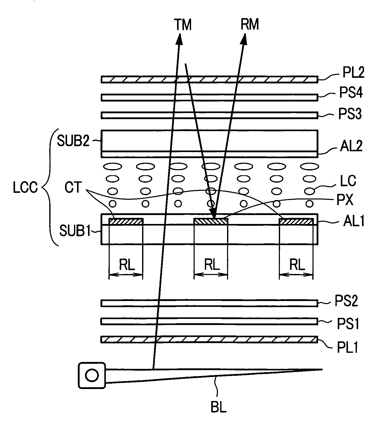
[0061]FIG. 6 is a cross-sectional view showing one embodiment of the liquid crystal display device according to the present invention. This embodiment shows an example in which the present invention is applied to a partial transmission type liquid crystal display device.

[0062] Here, with respect to a liquid crystal display panel (liquid crystal cell) LCC shown in FIG. 6, for facilitating the explanation, a cross section of only a portion which corresponds to one pixel among respective pixels which are arranged in a matrix array, for example is shown.

[0063] The liquid crystal display panel LCC is configured by adopting transparent substrates SUB1, SUB2 which are arranged to face each other with liquid crystal LC therebetween as an envelope. The transparent substrate SUB2 is arranged on a viewer's side (upper side in the drawing) a...


PUM


Abstract

The present invention provides a transmission-type, partial-transmission-type or a semi-transmission-reflection-type lateral electric field driving liquid crystal display device which can obtain the favorable transmissivity even when a circulatory polarized light is incident on a liquid crystal layer from a back surface side. In a liquid crystal display device which includes a first substrate which has a pixel electrode and a counter electrode, a second substrate which is arranged to face the first substrate in an opposed manner, a liquid crystal layer which is sandwiched between the first substrate and the second substrate, an upper polarizer which is arranged at a front surface side than the liquid crystal layer, and a lower polarizer which is arranged at a back surface side than the liquid crystal layer, the liquid crystal display device further includes a lower phase difference film which is arranged between the liquid crystal layer and the lower polarizer and converts a linearly polarized light to a circularly polarized light and an upper phase difference film which is arranged between the liquid crystal layer and the upper polarizer, the liquid crystal layer is driven by an electric field which is generated between the pixel electrode of the first substrate and the counter electrode of the first substrate, and a twist angle of the liquid crystal layer is within a range of 50° to 120° to perform a black display when a voltage is not applied.

Description

[0001] Priority is claimed based on Japanese Patent Application No. 2004-315519 filed on Oct. 29, 2004, all of which is incorporated by reference. [0002] The present application claims priority from Japanese application JP2004-315519 filed on Oct. 29, 2004, the content of which is hereby incorporated by reference into this application. BACKGROUND OF THE INVENTION [0003] The present invention relates to a liquid crystal display device, and more particularly to a liquid crystal display device having pixel electrodes and counter electrodes on a liquid-crystal-side pixel region of one substrate out of respective substrates which are arranged to face each other in an opposed manner with liquid crystal therebetween. [0004] This kind of liquid crystal display device is referred to as a so-called IPS type liquid crystal display device and is known as a display device which can drive liquid crystal based on components of an electric field which are arranged substantially parallel to the subs...

Claims


Application Information

Patent Timeline
IPC IPC(8): G02F1/1335
CPCG02F1/13363G02F1/1396G02F2001/133541G02F2001/133638G02F2001/1398G02F2413/04G02F1/133541G02F1/133638G02F1/1398G02F1/1335
Inventor MORIMOTO, MASATERUIMAYAMA, HIROTAKAOCHIAI, TAKAHIROITOU, OASAMU
Owner HITACHI DISPLAYS
Why Eureka
Try Eureka