
Perpendicular hard disk drive resistive against external magnetic field

a magnetic field and perpendicular technology, applied in the direction of shielding heads, magnetic recording, record carrier contruction details, etc., can solve the problems of recording information loss, interference with the operation of the hard disk drive (hdd) itself, etc., to prevent a decrease in magnetization or demagnetization, reduce and prevent the effect of stray field

Inactive Publication Date: 2006-05-04
HITACHI GLOBAL STORAGE TECH NETHERLANDS BV
View PDF10 Cites 2 Cited by
  • Summary
  • Abstract
  • Description
  • Claims
  • Application Information

AI Technical Summary

Benefits of technology

[0020] It is therefore a feature of the invention to provide a reliable apparatus for data storage system capable of preventing a decrease in magnetization or demagnetization from occurring to recording magnetization regardless of a direction in which a stray field is applied.
[0022] By so doing, when the stray field is applied in a direction perpendicular to the recording medium, the magnetic field shield installed in the vicinity of the main pole can shield the magnetic field. Alternatively, the magnetic field is caused to converge on the magnetic field, thereby alleviating the effect of the stray field on the main pole. When the stray field is applied in the horizontal direction in relation to the recording medium, the magnetic field applied to the soft under layer of the recording medium can be caused to take a detour toward the cover, thereby preventing the magnetic field from converging at respective ends of an auxiliary pole, and read shields, and at an end of the magnetic field shield in the vicinity of the main pole. As a result, in the case where a magnetic field is applied in either the perpendicular direction or the horizontal direction, it is possible to prevent a decrease in magnetization or demagnetization from occurring to the recording magnetization due to the effect of the stray field
[0023] With the invention, occurrence of a decrease in magnetization or demagnetization with respect to recording magnetization due to the stray field can be prevented regardless of a direction in which the stray field is applied, either in the perpendicular direction, or in the horizontal direction.

Problems solved by technology

If this phenomenon occurs, not only recorded information is lost, but also even a servo-mark and identification signals for tracks and sectors are lost in the extreme case, thereby raising a possibility of causing interference with operation of a hard disk drive (HDD) itself.
There have been long recognized problems occurring when a stray field in a direction perpendicular to a recording medium is applied.

Method used


Image

  • Perpendicular hard disk drive resistive against external magnetic field
  • Perpendicular hard disk drive resistive against external magnetic field
  • Perpendicular hard disk drive resistive against external magnetic field

Examples


embodiment 1

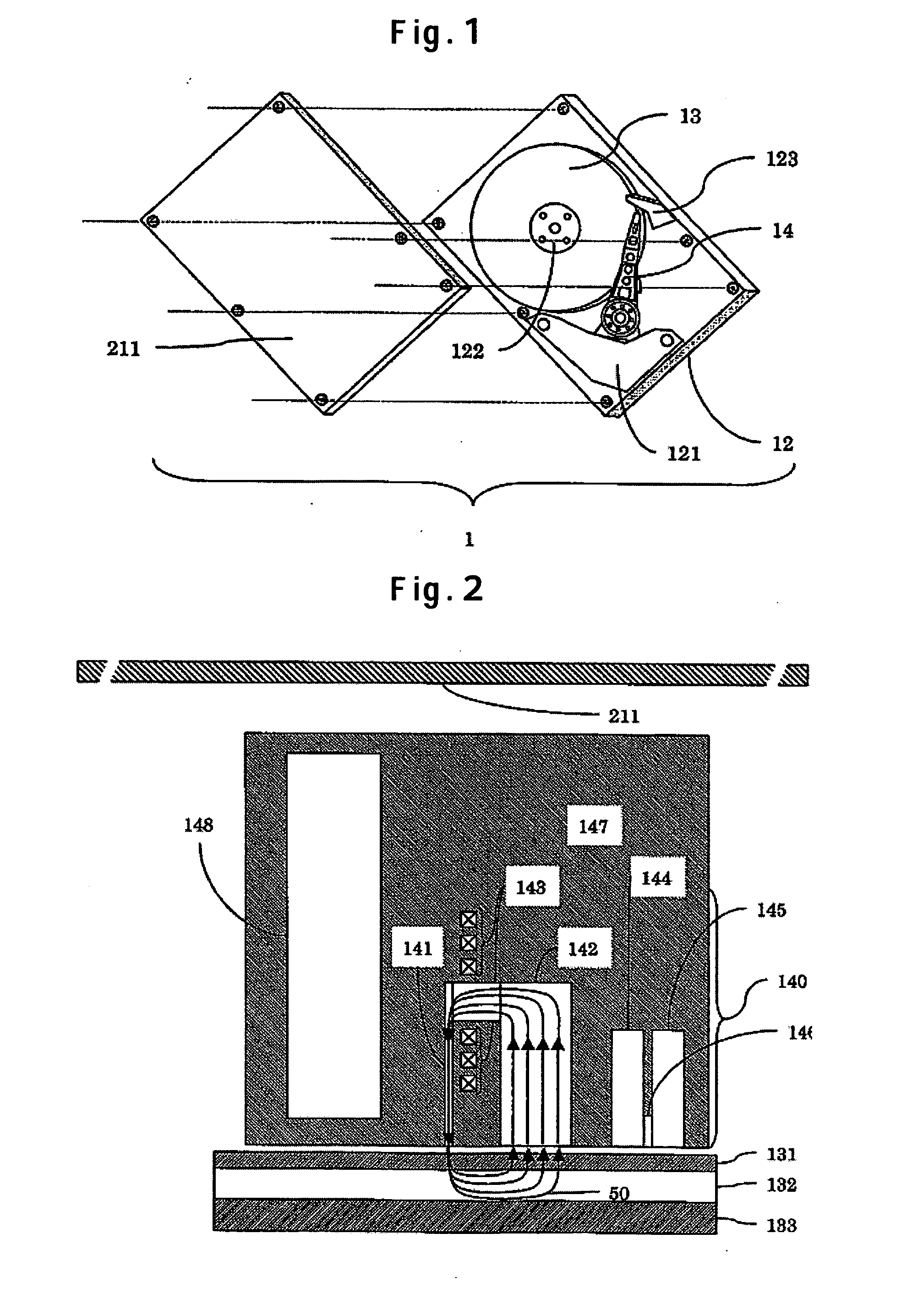
[0043]FIG. 1 is a schematic representation showing a first embodiment of a perpendicular magnetic hard-disk drive according to the invention. The perpendicular magnetic hard-disk drive 1 comprises a VCM 121, a spindle motor 122, a recording medium 13, a load beam 123, an HSA (Head Stack Assembly) 14, and so forth, disposed on a base 12. Those components are covered with a magnetic cover 211. A head 140 attached to the HSA 14 is a head with enhanced resistance to a stray field in the perpendicular direction.

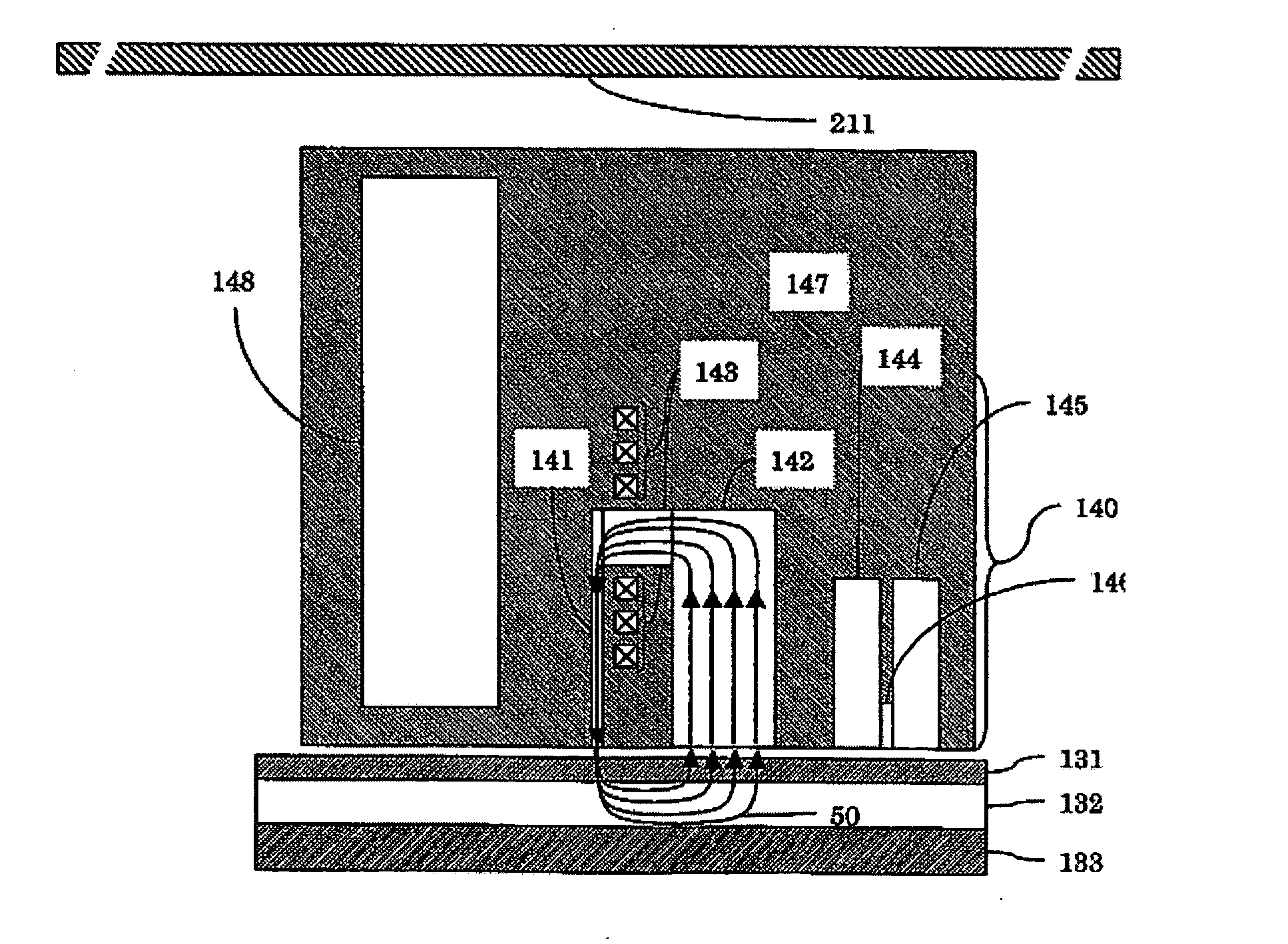
[0044]FIG. 2 is a schematic sectional view showing an example of the head with enhanced resistance to the stray field in the perpendicular direction, mounted in the perpendicular magnetic hard-disk drive 1 as shown in FIG. 1. A magnetic field shield 148 is installed in the vicinity of a main pole 141. The magnetic field shield 148 acts so as to cause the stray field otherwise flowing into the main pole 141 to converge toward the shield side of the head. Accordingly, the stray fie...

embodiment 2

[0048] There is described hereinafter a second embodiment of a perpendicular magnetic hard-disk drive comprising a head resistant to a stray field, having a magnetic field shield, and a magnetic cover.

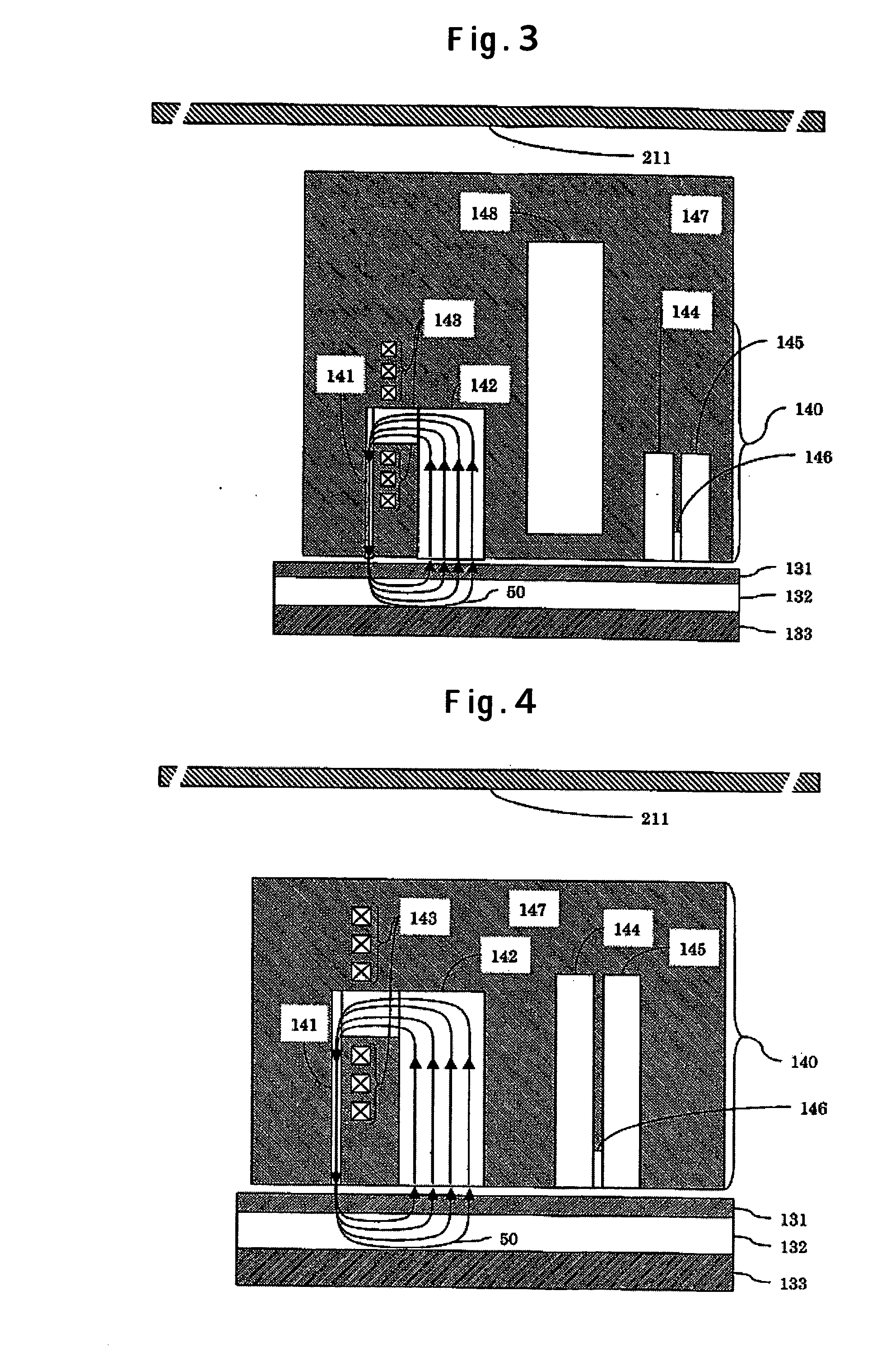
[0049]FIG. 3 is a schematic sectional view showing a head mounted in a perpendicular magnetic hard-disk drive having a magnetic cover 211. When the stray field in the horizontal direction is applied, the magnetic cover 211 causes a magnetic field applied to a head installed at an HSA 14, and a recording medium 13, inside the device, to converge on the cover. Further, when the stray field in the perpendicular direction is applied, a magnetic field shield 148 disposed between a write-head and a read-head causes the stray field flowing into a main pole 141 or an auxiliary pole 142 to converge on the magnetic field shield. Further, a magnetic field flowing into upper and lower read shields 144, 145 also can be similarly converged on the magnetic field shield 148.

[0050] With the present e...

embodiment 3

[0051] A configuration of a head having shields short in length, in the perpendicular direction, is described hereinafter as a third embodiment of the invention. FIGS. 4 and 5 are schematic sectional views each showing a head mounted in a perpendicular magnetic hard-disk drive having a magnetic cover 211. FIG. 4 shows a configuration wherein upper and lower read shields 144, 145 are long in the direction of an element height, and FIG. 5 shows a configuration wherein the upper and lower read shields 144, 145 are short in the direction of the element height. The head shown in FIG. 4 is the same in configuration as the head shown in FIG. 5 except that respective lengths of the upper and lower read shields 144, 145, in FIG. 4, differ from those in FIG. 5.

[0052]FIGS. 6 and 7 show difference in the effect of a stray field, due to difference in the lengths of the read shields, respectively. A main pole 141 is in a shape 170 nm in width on a face of the head used in this case, opposite to ...


PUM

PropertyMeasurementUnit
lengthaaaaaaaaaa
lengthaaaaaaaaaa
lengthaaaaaaaaaa

Abstract

Embodiments of the invention prevent a decrease in magnetization or demagnetization from occurring to recording magnetization regardless of a direction in which a stray field is applied. In one embodiment, an apparatus for data storage system comprises a head having a magnetic field shield in the vicinity of a main pole, and a cover of the device, using a constituent material with a magnetic field shielding effect, across the cover, or at part thereof. When a stray field in a direction perpendicular to a recording medium is applied, the effect of the magnetic field is alleviated by the magnetic field shield installed in the vicinity of the main pole. In such a case, it need only be sufficient to form the magnetic field shield in a shape optimum for removing the stray field in the perpendicular direction only. When a stray field in a direction horizontal in relation to the recording medium is applied, the magnetic field acting on the recording medium is removed by the cover of the device comprising a magnetic component.

Description

CROSS-REFERENCES TO RELATED APPLICATIONS [0001] This application claims priority from Japanese Patent Application No. JP2004-313711, filed Oct. 28, 2004, the entire disclosure of which is incorporated herein by reference. BACKGROUND OF THE INVENTION [0002] The present invention relates to an apparatus for data storage system for recording signals as magnetization in the direction of thickness of a magnetic recording medium, and magnetically reading the signals. [0003] The conventional recording technology is described hereinafter by taking an example of a perpendicular magnetic hard-disk drive. The perpendicular magnetic hard-disk drive refers to a magnetic hard-disk drive comprising a perpendicular recording medium, a read-write head, and so forth, for executing read-write by means of a perpendicular magnetic recording system. The perpendicular magnetic recording system is a system in which recording magnetization is formed in the direction of thickness of a medium in contrast to t...

Claims


Application Information

Patent Timeline
Patent Type & Authority Applications(United States)
IPC IPC(8): G11B17/00
CPCG11B5/11G11B5/1278G11B5/3143
Inventor HAMAGUCHI, TAKEHIKOKAMO, YOSHIHISAMAEDA, HIDEAKISHIMIZU, YUKIYATAGAWA, IKUYAYUKI, TETSUO
Owner HITACHI GLOBAL STORAGE TECH NETHERLANDS BV
Learn More