Powered hand held devices

a hand-held device and hand-held technology, applied in the field of hand-held devices, can solve the problems of inability to meet such variable energy and abandon consumer devices, and achieve the effect of being ready to be used for cutting

Inactive Publication Date: 2006-05-04
SUPERIOR TOOL CORP
View PDF35 Cites 90 Cited by
  • Summary
  • Abstract
  • Description
  • Claims
  • Application Information

AI Technical Summary

Benefits of technology

[0007] The present invention provides a powered hand held device having an improved power supply arrangement. The device preferably includes a power supply arrangement having both a high power source component and a low power source component. The high power source is preferably supplied by ultracapacitors. The power supply arrangement provides the lower power source as a battery source in parallel with the ultracapacitors for a supplementary power arrangement. Such an arrangement enables the use of the ultracapacitors by the device motor during certain peak power demands, which are somewhat infrequent, but require high power to the motor. The ultracapacitors provide supplemental power to the motor as needed during the cycle. Such supplementation reduces the load on the low power battery source, which is then able to run longer during low power continuous operation of the hand held device, and to extend battery life in situations where device operation is very intermittent.
[0009] Numerous powered hand held devices may potentially benefit from such a power supply arrangement, including household tools such as a coffee grinder or can opener, which have an initial peak power requirement which is used to initiate a longer, low power continuous cycle by a motor, such as a permanent magnet motor, which generally provides rotating operation during use of the device. Similarly, hand held toys or games which may use power, such as a bubble maker, or medical devices such as a hand held endoscopic device, use a motor with variable power requirements and may benefit from the present invention. Finally, powered hand held tools, such as plumbing tools for pipe or tube cutting or drain cleaning as well as hand held medical devices, also have improved power performance using the present invention.
[0010] An improved powered hand held tube cutter device of the present invention provides rapid tube cutting with less force applied to the tube being cut. The use of more revolutions, at less force, and optionally with a sharper cutting wheel, results in less burr to the tube being cut. The length of time the cutting wheel remains sharp is optionally improved using a cryogenic treatment. The cutter wheel assembly of the present device includes an adjustable rocking roller assembly, which may be moved to accommodate two different diameters of tubes to be cut. Additionally, the cutting wheel is housed within a cutter wheel housing which provides the cutting wheel in spring biased engagement with the tube to be cut. Engagement of the cutting wheel using an improved roller assembly for engaging the tube to be cut reduces displacement of the spring biased cutting wheel, resulting in a reduction of the spring force applied to the tube to be cut. Thus, the roller assembly retains the tube on one side, with the spring biased cutting wheel engaged with the tube on a side opposite the roller assembly. The present tool may be used with either the improved power supply arrangement previously described, or with a conventional power supply, such as rechargeable or disposable batteries, which are positioned within the tool handle assembly, or an AC power supply.
[0011] The improved device provides continuous 360° of rotation of the cutter wheel assembly relative to the tube being cut. Specifically, a door is provided which may be opened and closed once the tube is positioned within the tool cutter wheel assembly housing, and allows full rotation about an existing in-line piece of pipe or on a closed loop piping system. The door is moved to a “closed” position by the geometry of the cutter wheel housing once the tube is engaged within the tool, and is maintained in a “closed” position by a magnetic latch and the tool housing. Additionally, when the cutting operation is complete, the tool speed is reduced and tool operation is eventually stopped at a home position. The door is moved to an “open” position as the tool and tube are disengaged.
[0014] As shown in the attached figures, an angled handle is provided so that the tool device may readily used for cutting of in-line tubing in difficult to reach locations.

Problems solved by technology

Batteries alone were often unable to satisfy such variable energy requirements, and such proposed consumer devices were abandoned due to inadequate power supplies.

Method used


Image

  • Powered hand held devices
  • Powered hand held devices
  • Powered hand held devices

Examples


Embodiment Construction

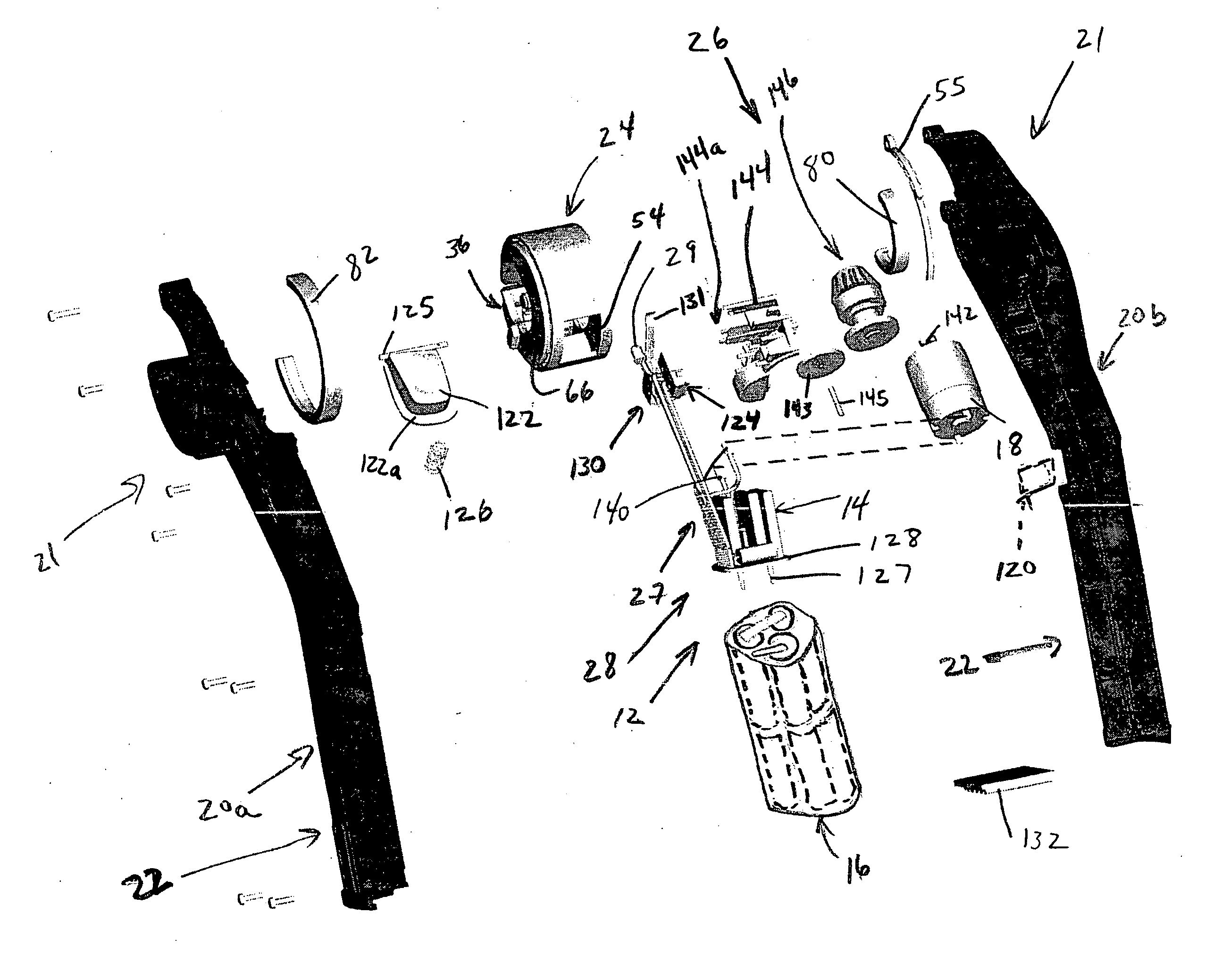
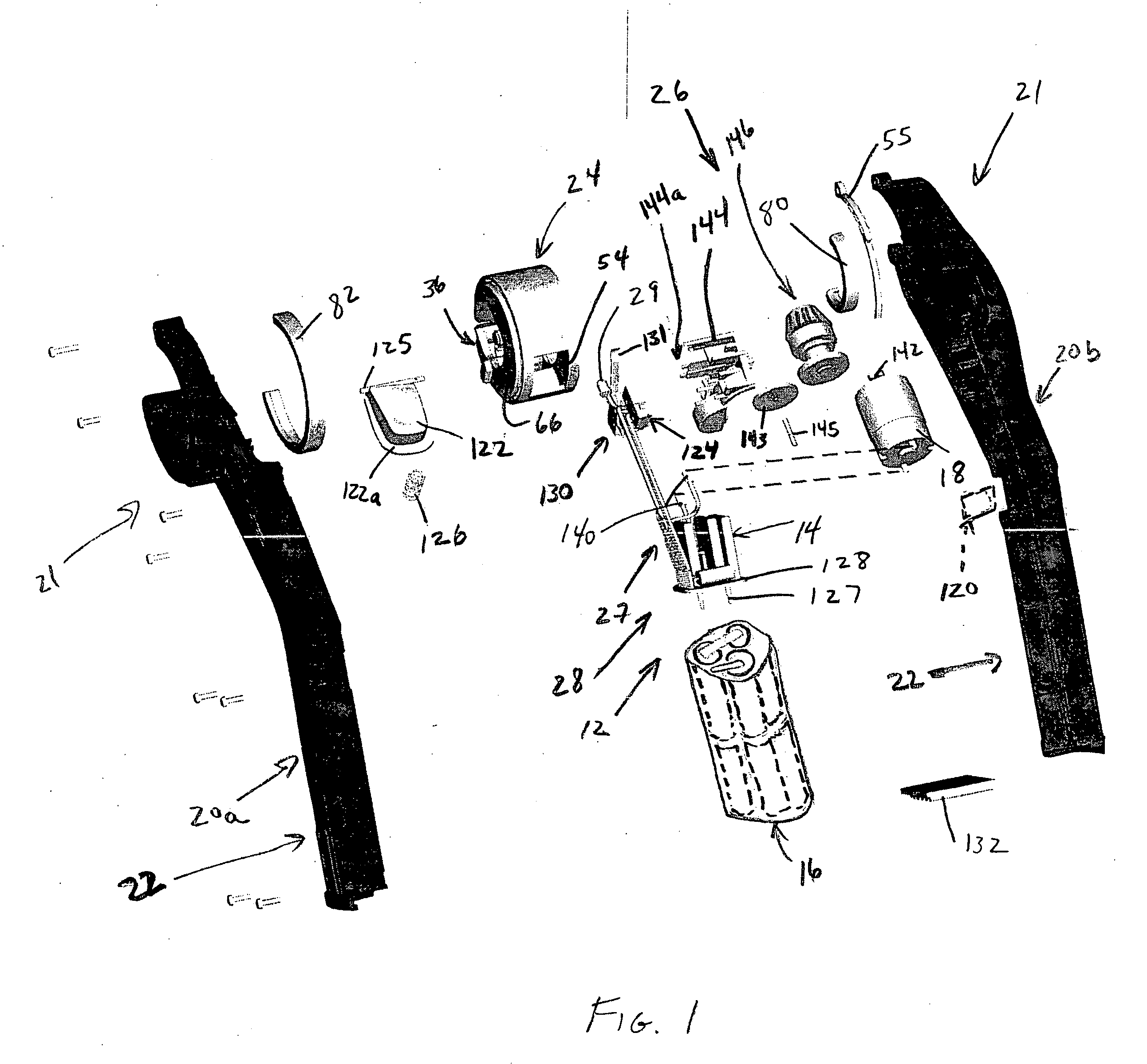
[0026]FIG. 1 discloses a powered hand held device 10 having an improved power supply arrangement 12 and an improved design for a tube or pipe cutter for use in plumbing or other applications. The power supply arrangement preferably has both a high power source component and a low power source component. In the embodiment of FIG. 1, the device is a powered hand held tube cutting device. The high power source is preferably supplied by ultracapacitors 14. The power supply arrangement provides the low power source, disclosed as a battery 16, in parallel with the ultracapacitors 14 for a supplementary power arrangement, as shown in FIG. 10. Such an arrangement enables the use of the ultracapacitors 14 by a motor 18 of the device 10 during certain peak power demands. The motor to be supplied with power may be a 110 Volt AC motor of the type manufactured by GE or Westinghouse corporations, but in the preferred embodiment is a 3.6 Volt permanent magnet DC motor available from Johnson Motors...


PUM

PropertyMeasurementUnit
rotationaaaaaaaaaa
widthaaaaaaaaaa
diameteraaaaaaaaaa

Abstract

A powered hand held device having an improved power supply with both a low power source in parallel with a high power source from ultracapacitors. The ultracapacitor power is used by the device motor during certain peak power demands which require high power to the device motor. An improved hand held tube cutter tool is provided both with and without the improved power arrangement, and includes a rotating cutter head assembly with an adjustable roller assembly providing a superior tube cut.

Description

CROSS REFERENCE TO RELATED APPLICATIONS [0001] The present application claims priority from U.S. Patent Application Ser. No. 60 / 624,044 filed Nov. 1, 2004, the entire subject matter of which is incorporated herein by reference.BACKGROUND OF THE INVENTION [0002] 1. Field of Invention [0003] The present invention is directed to hand held devices having specific power requirements, more specifically, powered hand held devices having motors supplying physical actuation during operation; such as hand tools, for use as plumbing tools such as tube cutters or drain cleaners, or medical devices; household tools, for example, can openers or toothbrushes; or hand held toys or games, such as bubble makers. [0004] 2. Background of the Related Art [0005] In the past, the development of hand held and / or portable consumer products required operating motors with both high power requirements during shorter term peaks of operation (for example, at the start or finish of a cycle), and longer, lower ene...

Claims


Application Information

Patent Timeline
Patent Type & Authority Applications(United States)
IPC IPC(8): H02M3/34
CPCA61B17/1628A61B2017/00734B23D21/04B25F5/00H02J7/345H02P7/20H02J2310/23B23D21/08
Inventor BELTON, JASON A.KOVACH, JAMES A.MINTZ, CHARLES J.PALMERTON, KIRK C.WALKER, RICK W.
Owner SUPERIOR TOOL CORP
Why Eureka
Try Eureka