Method for encoding and decoding video signals

a video signal and video technology, applied in the field of video signal encoding and decoding, can solve the problems of imposing a great burden on content providers, time delay in providing the requested signal to the mobile device, and difficulty in allocating such high bandwidth for the type of wireless transmission/reception performed by mobile phones and notebook computers

Inactive Publication Date: 2006-05-04
LG ELECTRONICS INC
View PDF3 Cites 55 Cited by
  • Summary
  • Abstract
  • Description
  • Claims
  • Application Information

AI Technical Summary

Benefits of technology

[0017] In one embodiment, the method calls for decoding an encoded video signal using a first frame sequence and a second frame sequence by inverse motion compensated temporal filtering. It is determined whether one or more macroblocks in at least one frame in the second frame sequence are associated with a current macro...

Problems solved by technology

While television broadcast signals require high bandwidth, it is difficult to allocate such high bandwidth for the type of wireless transmissions/receptions performed by mobile phones and notebook computers, for example.
This imposes a great burden on content providers.
However, this method entails a transcoding procedure including decoding, scaling and encoding processes, which causes some time delay in providing the req...

Method used


Image

  • Method for encoding and decoding video signals
  • Method for encoding and decoding video signals
  • Method for encoding and decoding video signals

Examples


Embodiment Construction

[0028] Example embodiments of the present invention will now be described in detail with reference to the accompanying drawings.

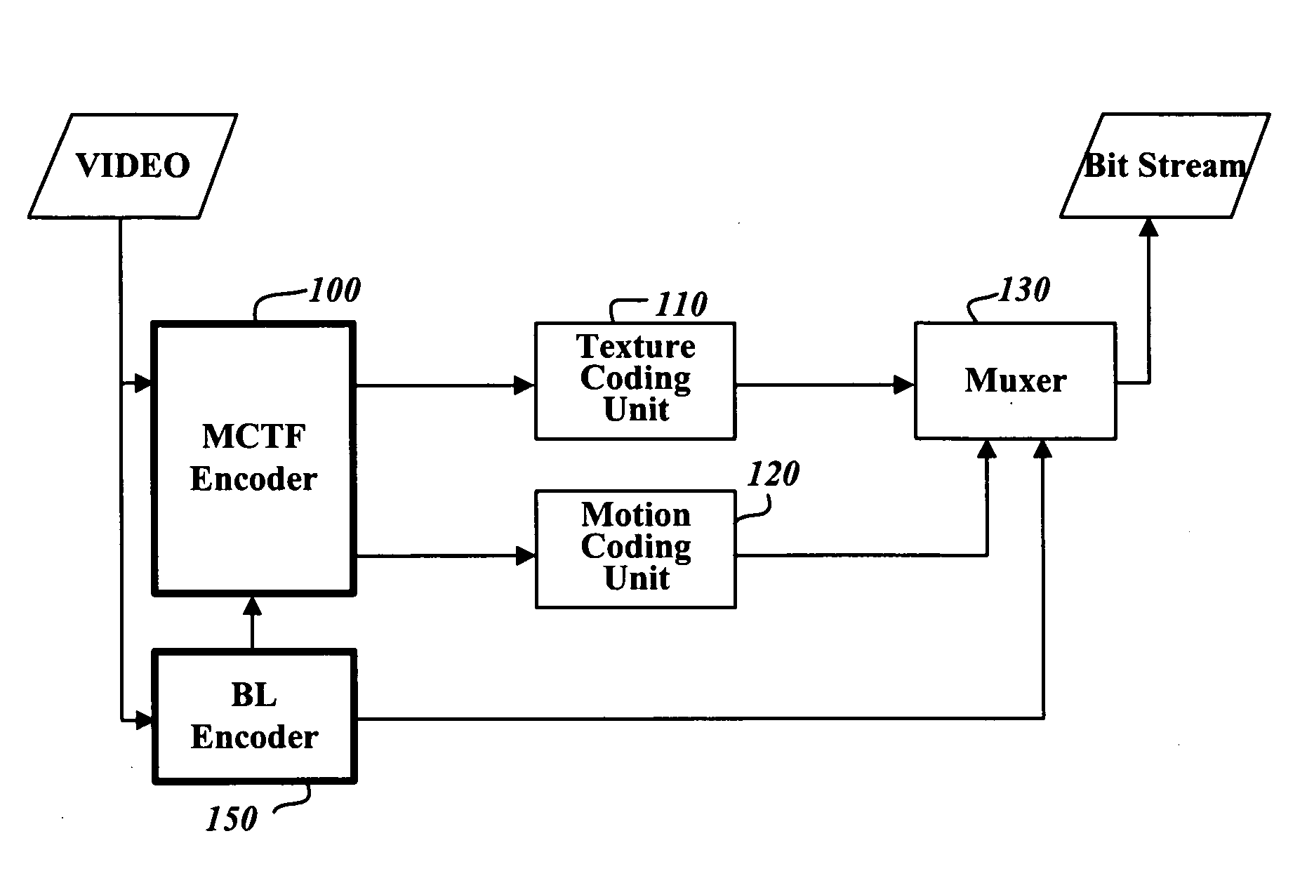
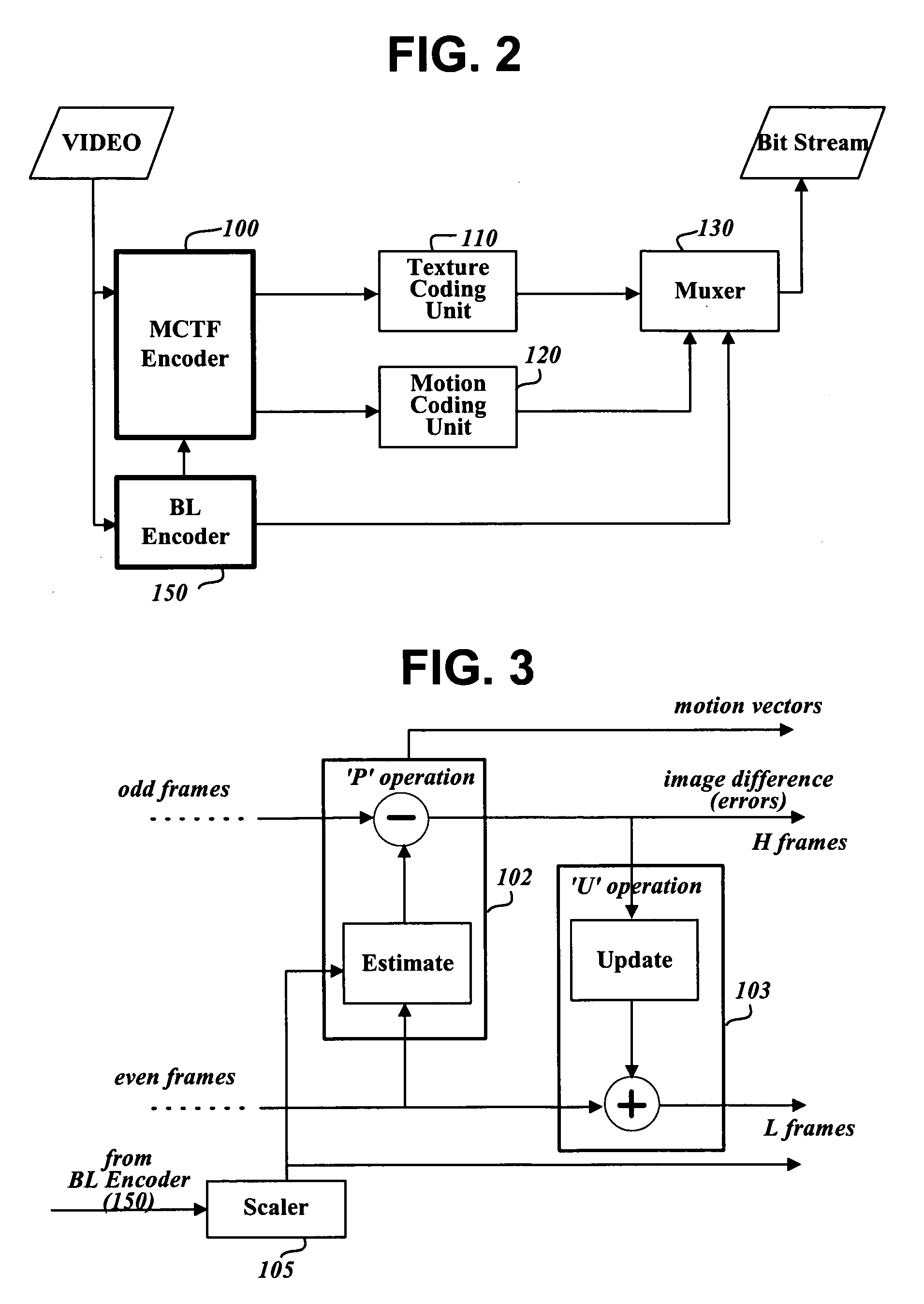
[0029]FIG. 2 is a block diagram of a video signal encoding device for applying a scalable video signal compression method according to an example embodiment of the present invention.

[0030] The video signal encoding device shown in FIG. 2 comprises an MCTF encoder 100, a texture coding unit 110, a motion coding unit 120, a base layer encoder 150, and a muxer (or multiplexer) 130. The MCTF encoder 100 encodes an input video signal in units of macroblocks in an MCTF scheme, and generates suitable management information. The texture coding unit 110 converts information of encoded macroblocks into a compressed bitstream. The motion coding unit 120 encodes motion vectors of macroblocks obtained by the MCTF encoder 100 into a compressed bitstream according to a specified scheme. The base layer encoder 150 encodes an input video signal according to a specified sc...


PUM


Abstract

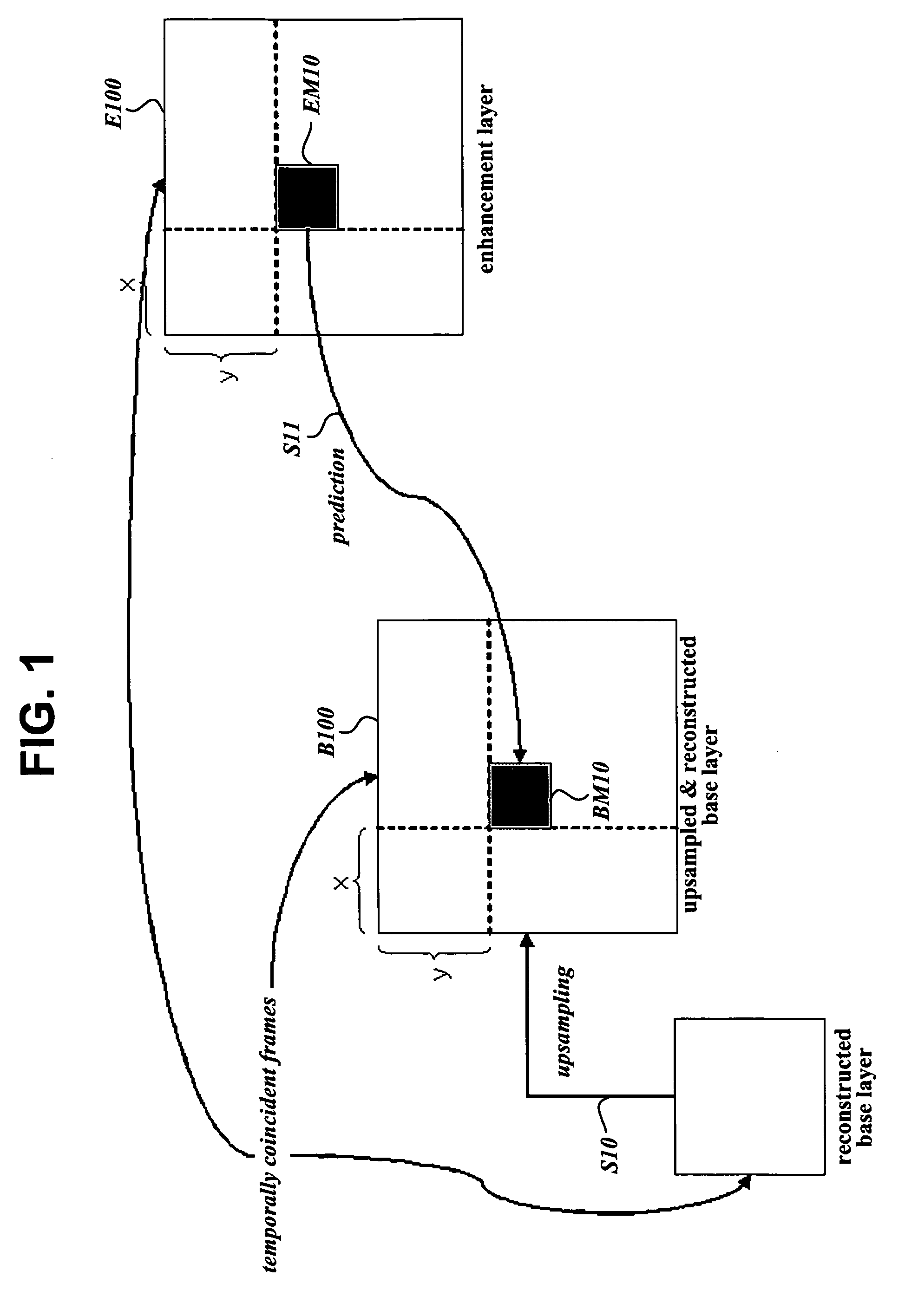
A method for encoding video signals by inverse motion compensated temporal filtering where video frames of a base layer are used to encode video frames of an enhanced layer into predicted images. For each image block in an arbitrary frame in an enhanced layer frame sequence, an area including a block, which is present in a base layer frame temporally coincident with the arbitrary frame and is at the same position as the image block, is enlarged according to the ratio between screen sizes of the two layers. A reference block most highly correlated with the image block is searched for in the enlarged area in the temporally coincident base layer frame through motion estimation and is used to obtain pixel difference values and a motion vector of the image block for encoding the image block into a predicted image, thereby improving coding efficiency.

Description

PRIORITY INFORMATION [0001] This application claims priority under 35 U.S.C. §119 on Korean Patent Application No. 10-2005-0014843, filed on Feb. 23, 2005: the entire contents of which are hereby incorporated by reference. [0002] This application also claims priority under 35 U.S.C. §119 on U.S. Provisional Application No. 60 / 621,688, filed on Oct. 26, 2004; the entire contents of which are hereby incorporated by reference.BACKGROUND OF THE INVENTION [0003] 1. Field of the Invention [0004] The present invention relates to a method for encoding and decoding video signals using scalable Motion Compensated Temporal Filtering (MCTF). [0005] 2. Description of the Related Art [0006] While television broadcast signals require high bandwidth, it is difficult to allocate such high bandwidth for the type of wireless transmissions / receptions performed by mobile phones and notebook computers, for example. Thus, video compression standards for such devices must have high video signal compression...

Claims


Application Information

Patent Timeline
IPC IPC(8): H04N7/12H04N11/04H04B1/66H04N11/02H04N19/30
CPCH04N19/31H04N19/615H04N19/33H04N19/63H04N19/61H04N19/13B28B7/0029B28B7/30B28B21/82B28B21/88E02D29/12E02D2250/0007
Inventor PARK, SEUNG WOOKPARK, JI HOJEON, BYEONG MOON
Owner LG ELECTRONICS INC
Why Eureka
Try Eureka