
Fuel cell system and method of controlling idle stop of the fuel cell system

a fuel cell and idle stop technology, applied in the direction of fuel cells, cell components, electrical equipment, etc., can solve the problems of unstable electricity generation, achieve the effect of improving the fuel cell system, generating electricity stably, and moving smoothly

Active Publication Date: 2006-05-04
HONDA MOTOR CO LTD
View PDF2 Cites 32 Cited by
  • Summary
  • Abstract
  • Description
  • Claims
  • Application Information

AI Technical Summary

Benefits of technology

[0011] In the aforementioned fuel cell system according to the first aspect, the operation temperature of the fuel cell is detected during the idle stop of the fuel cell, and in accordance with the detected operation temperature, the fuel cell is preferentially kept in the electricity generation state from the idle stop state. Therefore, it is possible to improve the fuel cell system so that generation of electricity by the fuel cell does not become unstable.
[0012] Since the fuel cell stably generates electricity and the fuel cell mounted movable body can move smoothly, it is possible to keep driving characteristics of the fuel cell mounted movable body and to prevent driveability from being impaired.
[0017] In the aforementioned fuel cell system according to the second aspect, it is possible to probe the cause of lowering cell voltage and to appropriately prohibit idle stop. As a result, effective operation of the fuel cell and improvement of fuel economy can be achieved.
[0025] In the aforementioned controlling method according to the first aspect, the operation temperature of the fuel cell is detected during the idle stop of the fuel cell, and in accordance with the detected operation temperature, the fuel cell is preferentially kept in the electricity generation state from the idle stop state. Therefore, it is possible to improve the fuel cell system so that generation of electricity by the fuel cell does not become unstable.
[0026] Since the fuel cell stably generates electricity and the fuel cell mounted movable body can move smoothly, it is possible to keep driving characteristics of the fuel cell mounted movable body and to prevent driveability from being impaired.
[0030] In the aforementioned controlling method according to the second aspect, it is possible to probe the cause of lowering cell voltage and to appropriately prohibit idle stop. As a result, effective operation of the fuel cell and improvement of fuel economy can be achieved.

Problems solved by technology

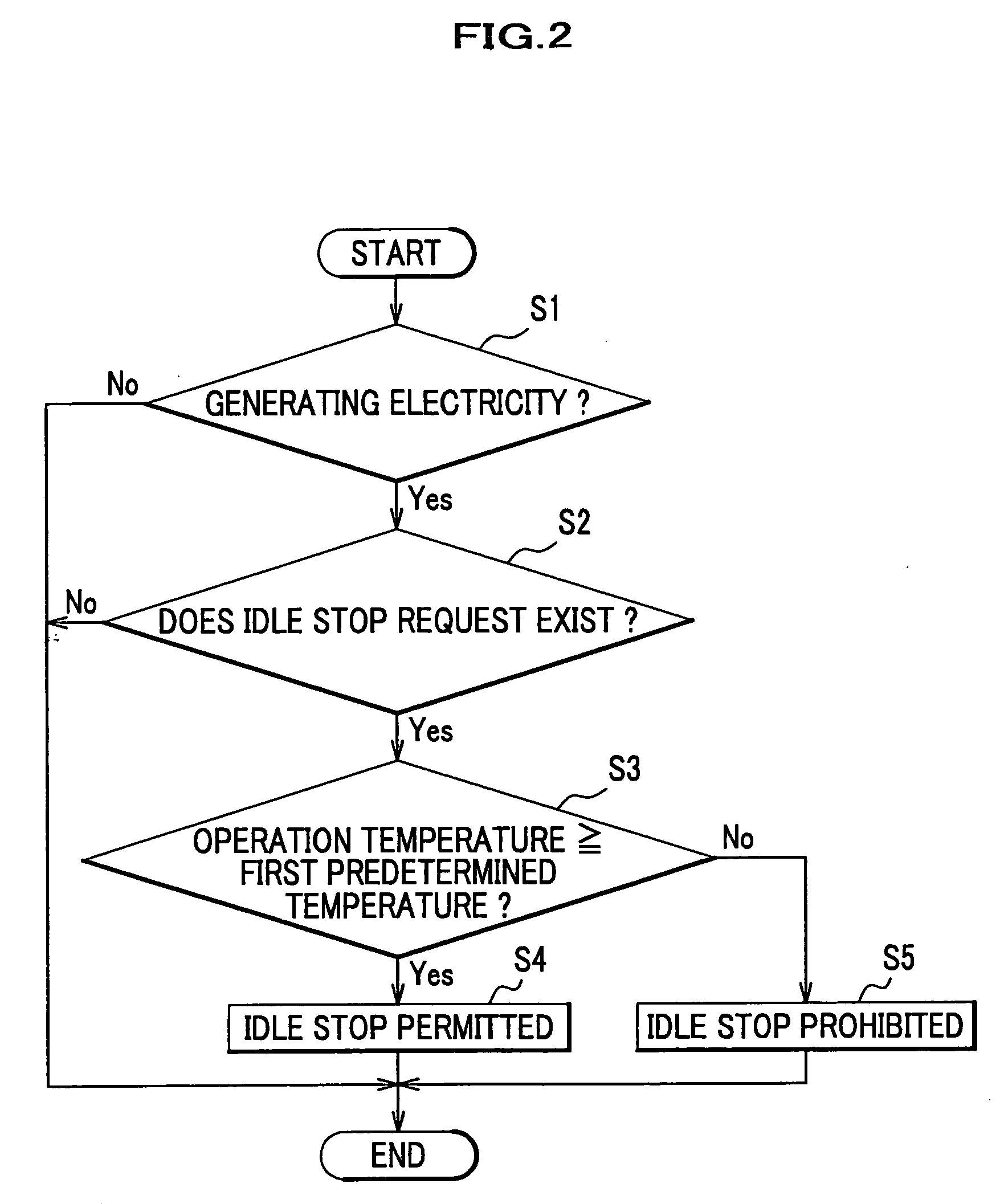
The unstable state detection means may determine that the generation of electricity is unstable if the operation temperature detected by the temperature sensing means is lower than the first predetermined temperature.

Method used


Image

  • Fuel cell system and method of controlling idle stop of the fuel cell system
  • Fuel cell system and method of controlling idle stop of the fuel cell system
  • Fuel cell system and method of controlling idle stop of the fuel cell system

Examples


first embodiment

Construction of Fuel Cell Vehicle

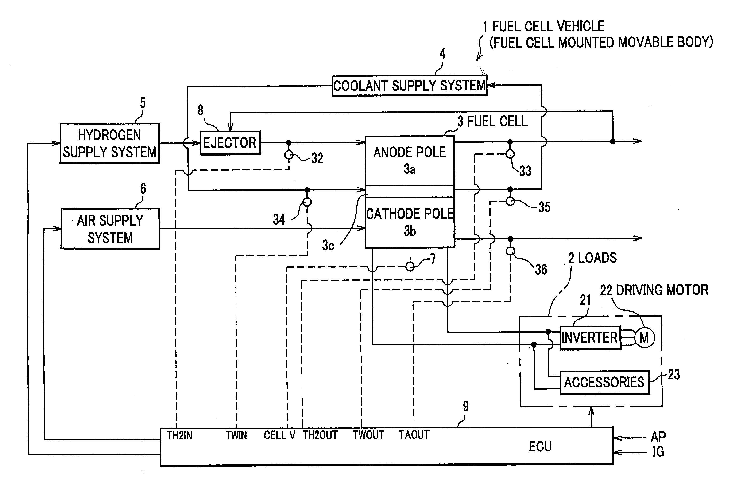
[0039] With reference to the block diagram shown in FIG. 1, the construction of a fuel cell vehicle 1 will be described.

[0040] The fuel cell vehicle 1 includes loads 2 as a source of power to move a vehicle body (not shown), a fuel cell 3 which supplies electric power to the loads 2, a coolant supply system 4 which supplies coolant to the fuel cell 3, a hydrogen supply system 5 which supplies hydrogen to the fuel cell 3, and an air supply system 6 which supplies air to the fuel cell 3.

[0041] The fuel cell vehicle 1 also includes temperature sensing means for detecting an operation temperature of the fuel cell 3 (inlet hydrogen temperature sensor 32, outlet hydrogen temperature sensor 33, inlet water temperature sensor 34, outlet water temperature sensor 35, and outlet air temperature sensor 36).

[0042] The fuel cell vehicle 1 includes a cell voltage detector 7 and an ejector 8.

[0043] Further, the fuel cell vehicle 1 is provided with ECU (Electro...

second embodiment

[0075] In a fuel cell system equipped with a fuel cell, loads, and an electricity storage means (battery, capacitor or the like), voltage of single cells that form part of the fuel cell drops by the following two causes (cause 1 and cause 2). Idle stop control can be prohibited properly if these causes are determined.

[0076] To be more specific, voltage (cell voltage) is different between a single cell whose electric poles are supplied with sufficient reaction gas (fuel gas, oxidant gas) and a single cell whose electric poles are supplied with insufficient reaction gas. In a single cell whose electric poles are supplied with insufficient reaction gas, voltage is relatively low. For example, if the electric pole(s) of a single cell is covered with water, supply of reaction gas to the electrode becomes insufficient and the voltage of the single cell lowers. This is classified into Cause 1. Normally, water is discharged from the single cell by an air flow of the supplied reaction gas. ...


PUM

PropertyMeasurementUnit
speedaaaaaaaaaa
temperatureaaaaaaaaaa
temperature sensingaaaaaaaaaa

Abstract

A fuel cell system and an idle stop controlling method for the fuel cell system. The fuel cell system includes: a fuel gas supply means for supplying fuel gas; an oxidant gas supply means for supplying oxidant gas; a fuel cell to which the fuel gas and the oxidant gas are supplied for generation of electricity; an idle stop means for stopping generation of electricity by the fuel cell to perform idle stop; and an unstable state detection means for detecting whether the generation of electricity by the fuel cell is unstable. If the unstable state detection means detects that generation of electricity by the fuel cell is unstable, idle stop by the idle stop means is prohibited so that the fuel cell continues to generate electricity.

Description

CROSS REFERENCE TO RELATED APPLICATIONS [0001] This application claims the foreign priority benefit under Title 35, United States Code, §119(a)-(d) of Japanese Patent Application Nos. 2004-319316 and 2004-343197, filed on Nov. 2, 2004 and Nov. 26, 2004 in the Japan Patent Office, the contents of which are hereby incorporated by reference. BACKGROUND OF THE INVENTION [0002] The present invention relates to an idle stop controlling technique for stopping generation of electricity of a fuel cell system which is mounted on a fuel cell mounted movable body such as automobiles and railroad vehicles. [0003] To improve fuel economy, so-called idle stop control is carried out for a fuel cell vehicle which mounts a fuel cell system. The idle stop control is carried out, for example, by stopping a part of accessories for supplying reaction gas to the fuel cell, such as a compressor, during the stop of the vehicle. For example, Japanese Laid-open Patent Application No. 2001-359204 (see paragrap...

Claims


Application Information

Patent Timeline
Patent Type & Authority Applications(United States)
IPC IPC(8): H01M8/04
CPCH01M8/04328H01M8/04343H01M8/0435H01M8/04358H01M8/04365H01M8/04552H01M8/04873H01M8/04955H01M8/04992Y02E60/50
Inventor IGARASHI, DAISHIMURAKAMI, YOSHIKAZUUEHARA, JUNJIUEDA, KENICHIROSAITOH, DAIWAKE, CHIHIRO
Owner HONDA MOTOR CO LTD
Learn More