Battery module

a battery module and battery technology, applied in the field of battery modules, can solve the problems of increasing the overall volume of the battery module, difficult to radiate the heat generated in the unit battery, and difficulty in assembling the battery, so as to improve the assembling quality of the unit battery, prevent irregular changes in characteristics, and improve the effect of safety

Inactive Publication Date: 2006-05-04
SAMSUNG SDI CO LTD
View PDF7 Cites 105 Cited by
  • Summary
  • Abstract
  • Description
  • Claims
  • Application Information

AI Technical Summary

Benefits of technology

[0015] The present invention provides a battery module capable of keeping installation positions of partition walls constant and capable of inducing uniform deformation of the partition walls and a case, by securely fixing the partition walls within the case or by forming the partition walls integrally with the case.
[0016] The present invention also provides a battery module capable of preventing the positional movement of the battery units by forming a battery fixing structure to improve the engaging force between the case and the unit batteries or between the case and the partition walls.

Problems solved by technology

Since the battery module is constructed by connecting several or tens of unit batteries to each other, the battery module has a problem in that its overall volume is increased because the typical battery module needs a cooling structure, a safety means, a system circuit, etc., which are adapted to be easily capable of radiating heat generated in each unit battery.
In order to solve the problem, a method of reducing the size of the battery module by reducing the interval between the unit batteries is used, but this causes another problem in that it is difficult to radiate the heat generated in the unit batteries.
If the heat generated in the respective unit batteries cannot be efficiently radiated, this will increase the temperature which will result in malfunction of apparatuses to which the battery module is applied.
If the size of the battery modules is increased, there is a problem in that not only the weight of the battery modules increases but also the design of the apparatuses (particularly, vehicles) equipped with the battery modules becomes complex.
However, such a conventional battery module has problems in that, when an external force is applied, nonuniform deformation may occur in the battery module, which may lower reliability of the battery module, making it difficult to hold installation positions of the partition walls (interval between the partition walls) constant, and to prevent positional movement of the unit batteries.

Method used


Image

  • Battery module
  • Battery module
  • Battery module

Examples


fifth embodiment

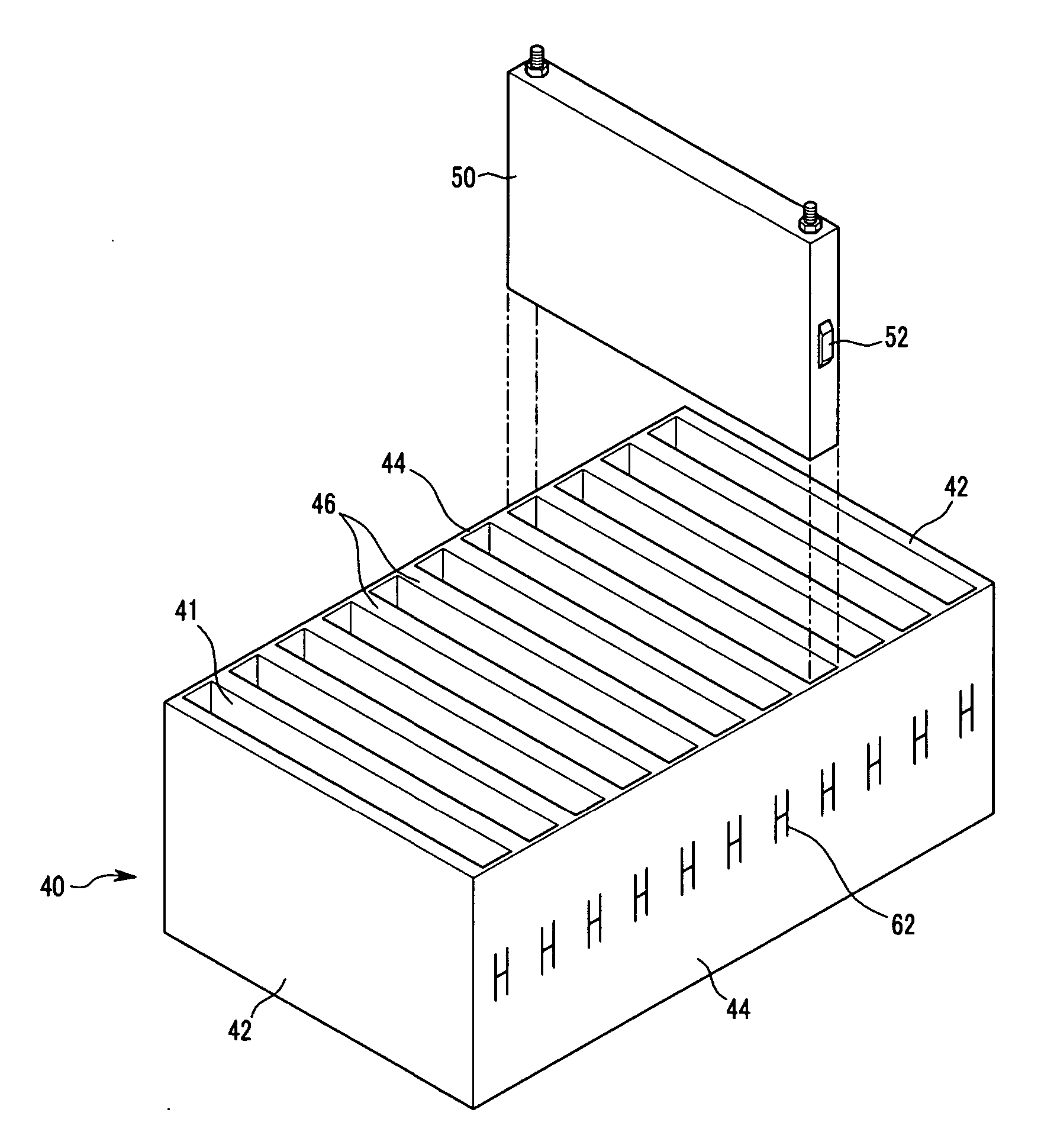
[0083]FIG. 9 is an enlarged sectional view showing a battery fixing structure of a battery module according to the present invention.

[0084] As shown in FIGS. 7 and 9, the battery fixing structure has fixing projections 52 formed so as to protrude from the side faces of the unit batteries 50 which face the case 40 and, in particular, cutouts 62 formed at positions of the side plates 44 of the case 40 corresponding to the fixing projections 52. Cutouts 62 may be formed by cutting the case in the shape of the letter “H”.

[0085] In an exemplary embodiment at least front faces of the fixing projections 52 in their insertion direction may be formed having inclined surfaces so that the fixing projections can be easily inserted. Accordingly, the fixing projections 52 may have trapezoidal side faces, or otherwise may have side faces in various shapes, such as a rectangular shape, a triangular shape, a semicircular shape, and a semispherical shape.

[0086] In an exemplary embodiment the side p...

eighth embodiment

[0093]FIG. 12 is an exploded perspective view showing a battery module according to the present invention, and FIG. 13 is a sectional view of the battery module of FIG. 12 in an assembled configuration. The battery fixing structure according to the present invention includes fixing projections 57 formed so as to protrude from the side faces of the unit batteries 50′ on the side of the partition walls 46′, and fixing grooves 67 formed at positions of the partition walls 46′ corresponding to the fixing projections 57 for allowing the fixing projections 57 to be inserted therethrough.

[0094] In an alternative embodiment, fixing grooves may be formed on the side faces of the unit batteries which face the partition walls and fixing projections may be formed at positions of the partition walls corresponding to the fixing grooves.

[0095] In still another embodiment, the battery fixing structure may be installed not only between the unit batteries and the partition walls but also between the...

tenth embodiment

[0101]FIG. 15 is an exploded perspective view showing a battery module according to the present invention. Two rows of battery fixing structures are formed in the battery module according to the present embodiment.

[0102] Specifically, two rows, i.e., upper and lower rows of fixing projections 52 are formed so as to protrude from the side faces of the unit batteries 50″ which face the case 40 and two rows 76, 78 of cutouts 63 are formed at positions of the side plates 74 of the case 40 corresponding to the fixing projections 52 and formed by cutting the case substantially in the shape of the letter “H”.

[0103] Also, three more rows of the fixing projections 52 and the cutouts 63 may be formed.

[0104] Since the same battery installation configuration as the sixth to ninth embodiments can also be embodied in the above-described tenth embodiment, its detailed description will be omitted.

[0105] The battery modules according to the embodiments of the present invention configured as descr...


PUM

PropertyMeasurementUnit
thicknessaaaaaaaaaa
volumeaaaaaaaaaa
sizeaaaaaaaaaa

Abstract

A battery module includes a case with at least one face which is opened, a plurality of partition walls fixedly installed at predetermined intervals in the case, and a plurality of unit batteries which are separated from each other with the partition walls therebetween to be inserted into the case. The battery module may include a battery fixing structure which is installed between the case and the unit batteries to fix the unit batteries so as to prevent positional movement of the unit batteries in the case. The battery fixing structure may be a concavo-convex engaging structure including fixing projections and projection receiving portions.

Description

CROSS-REFERENCE TO RELATED APPLICATION [0001] This application claims priority to and the benefit of Korean Patent Application Nos. 10-2004-0086602 and 10-2004-0086603, both filed with the Korean Intellectual Property Office on Oct. 28, 2004, the entire contents of which are incorporated herein by reference. BACKGROUND OF THE INVENTION [0002] 1. Field of the Invention [0003] The present invention relates to a battery module, and more particularly, to a battery module capable of holding partition walls at fixed installation positions and enhancing an engaging force of the unit batteries within a case. [0004] 2. Related Art [0005] Generally, secondary batteries are rechargeable and can be repeatedly used. In particular, secondary batteries including only one battery cell are mainly used for various small portable electronic apparatuses, such as cellular phones, laptop computers, cameras, and camcorders. High-capacity secondary batteries (hereinafter referred to as a ‘battery module’) ...

Claims


Application Information

Patent Timeline
Patent Type & Authority Applications(United States)
IPC IPC(8): H01M2/10H01M6/42H01M50/209H01M50/289
CPCH01M2/1072H01M6/42H01M10/0413H01M10/0472Y02E60/10H01M50/209H01M50/289
Inventor JEON, YOON-CHEOLLEE, GUN-GOOKIM, TAE-YONG
Owner SAMSUNG SDI CO LTD
Why Eureka
Try Eureka