Circuit link connector

a technology of circuit link and connector, which is applied in the direction of coupling device connection, electrical discharge lamp, coupling device details, etc., can solve the problems of limiting the location, limiting the dimensions and shape of the housing, and limiting the size of the housing, so as to reduce the wiring requirements of power distribution units, increase the transmission capacity of layers, and increase the space

Inactive Publication Date: 2006-05-04
SERVER TECHNOLOGY
View PDF10 Cites 16 Cited by
  • Summary
  • Abstract
  • Description
  • Claims
  • Application Information

AI Technical Summary

Benefits of technology

[0016] Certain embodiments of the present invention may provide power distribution units having reduced amounts of wiring. Wiring reduction can occur in a number of ways. First, in certain embodiments, electronic components are connected to power supplies or circuit links (such as fuses or circuit breakers) through the circuit link interconnection board. The use of the circuit link interconnection board can obviate the need for discreetly wiring each electronic component.
[0028] In a fourteenth embodiment, the circuit link interconnection board includes a ground connection for a circuit of the circuit link interconnection board. A fastener opening may be formed in the circuit link interconnection board and in communication with the circuit. A fastener may be inserted through the fastener opening and coupled to a ground, such as the housing of a power distribution unit. The use of the fastener as a ground connection may reduce the wiring requirements of power distribution units according to this embodiment because this embodiment may obviate wiring a separate ground connection.

Problems solved by technology

Typically, all of these electronic components must be wired together, which can create numerous problems and inefficiencies.
One such problem is that the size of the electronic components and the associated wiring may limit the dimensions and shape of the housing.
The size of the housing can limit the locations in which the power distribution unit can be mounted.
For example, the power distribution unit may be too large for certain spaces.
The size of the components and wiring may limit how many and what kind of components can be included in a power distribution unit.
Another problem with such prior art power distribution units is that they often require substantial time and effort to assemble because each electronic component is typically individually mounted in the housing.
In addition to possibly requiring greater assembly time, the numerous parts and connections in typical prior art power distribution units may result in a greater number of errors during the manufacturing process or a greater chance of equipment failure once the power distribution units are in use.
Another problem with some prior art power distribution units stems from the fuses or other devices that are typically used to protect the power distribution unit and attached electronic devices against current fluctuations.
In addition to possibly being time consuming and labor intensive, opening up the unit may violate a warranty on the unit.
Branched circuit protection may result in an increased number of fuses in each power distribution unit, thus potentially increasing the size of, and the amount of wiring in, the power distribution unit.
The crossed wires may make the assembly of the power distribution unit more complex and may require more space in the housing.

Method used


Image

  • Circuit link connector
  • Circuit link connector
  • Circuit link connector

Examples


Embodiment Construction

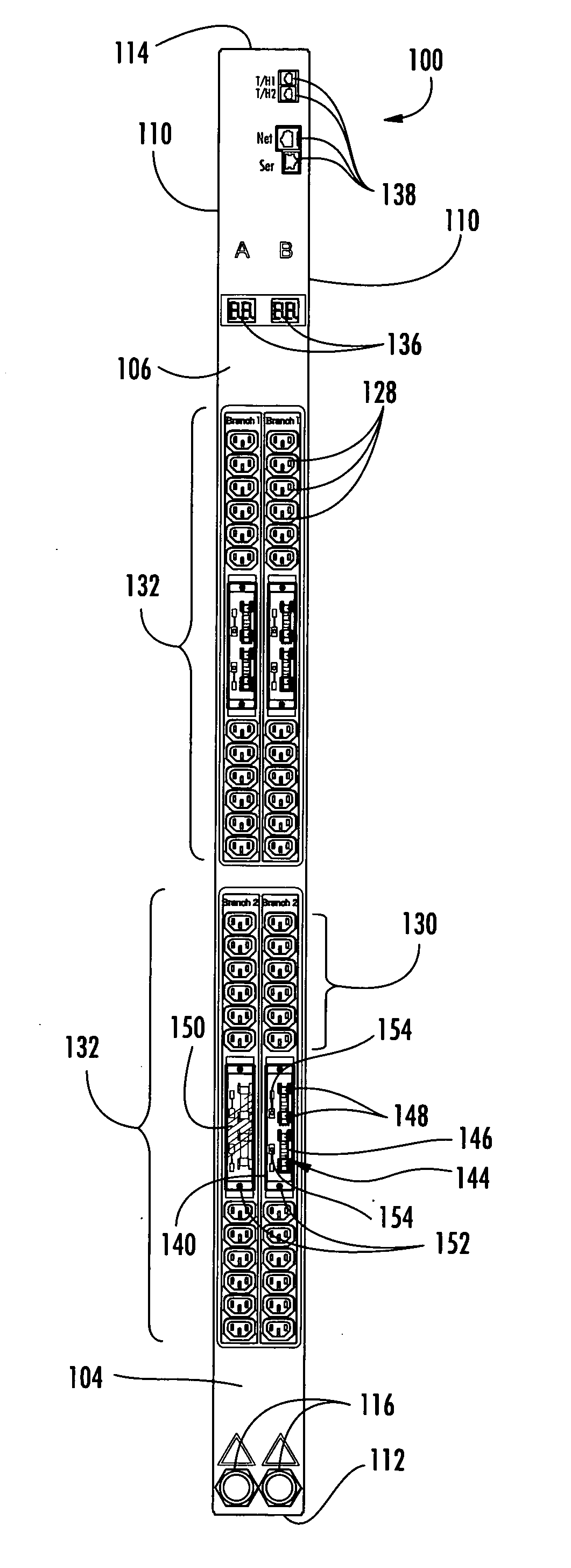
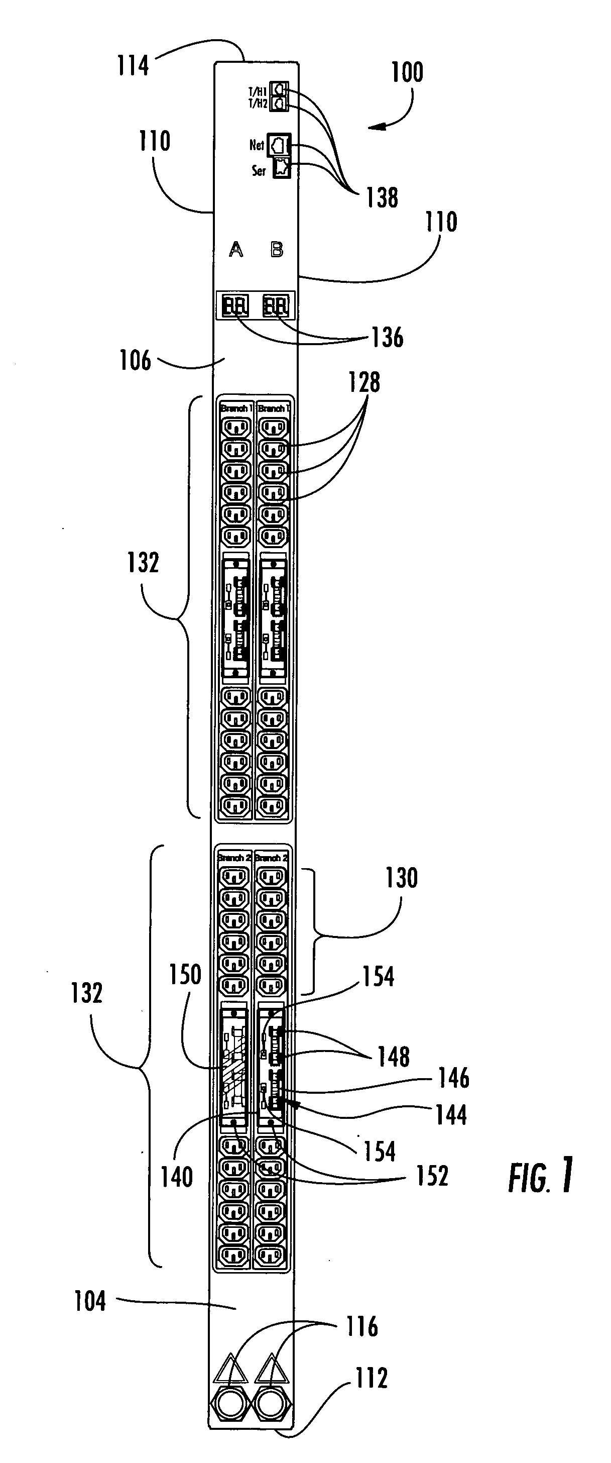
[0040] A power distribution apparatus (PDA) 100 according to an embodiment of the present invention is shown in FIG. 1. The PDA 100 may be mounted to a rack (not shown). The PDA 100 has a housing 104. The housing 104 may be of any suitable dimensions. The housing 104 is preferably sized for mounting to a rack. The housing 104 is shown as a rectangular box having longitudinally extending front 106 and back 108 (FIG. 3) faces, two longitudinally extending lateral sides 110, a first end 112, and a second end 114. Of course, shapes other than rectangular boxes could be used.

[0041] The housing 104 is made of a substantially rigid and durable material, such as metals or plastics, including polycarbonate resins. In at least one embodiment, the housing 104 is made of sheet metal.

[0042] Two power inputs 116 are coupled to the housing 104. Although two power inputs 116 are shown, more or less power inputs 116 could be used. In the illustrated embodiment, the power inputs 116 are connected t...


PUM


Abstract

Certain embodiments provide a power distribution unit that may be used to distribute power to a plurality of electronic devices. The power distribution unit may have one or more outlet gangs, integral components having a plurality of individual power outlets. Each outlet gang may be associated with one or more power rails which deliver power to each power outlet. A connector may be located on each power rail. The power distribution unit may include a circuit link interconnection board for connection to one or more electronic components, such as outlet gangs. A circuit link is coupled to the circuit link interconnection board and fuseably protects at least one circuit of the interconnection board. Access windows may be provided to provide access to the circuit link.

Description

CROSS REFERENCE TO RELATED APPLICATION [0001] The present application claims the benefit of, and hereby expressly incorporates by reference in its entirety, U.S. Provisional Patent Application No. 60 / 624,286, filed Nov. 1, 2004, and entitled “POWER DISTRIBUTION APPARATUS,” by Ewing et al.TECHNICAL FIELD [0002] The present invention relates to circuit link connectors. Certain embodiments provide power distribution apparatus utilizing such circuit link connectors. BACKGROUND [0003] Electronic equipment racks commonly consist of rectangular or box-shaped housings or rack structures. Electronic equipment is commonly mountable in such racks so that the various electronic components are aligned vertically one on top of the other in the rack. Often, multiple racks are oriented side-by-side, with each rack containing numerous electronic components and having substantial quantities of associated component wiring located both within and outside of the area occupied by the racks. [0004] Power ...

Claims


Application Information

Patent Timeline
Patent Type & Authority Applications(United States)
IPC IPC(8): H01R25/00
CPCH01R9/226H01R13/6658H01R13/68H01R25/00
Inventor EWING, CARROL W.CLEVELAND, ANDREW J.MASKALY, JAMES P.MCGLUMPHY, DENNIS W.MOLL, NATHAN
Owner SERVER TECHNOLOGY
Why Eureka
Try Eureka