Base station apparatus and communication terminal apparatus

Active Publication Date: 2006-05-04
GK BRIDGE 1
View PDF5 Cites 22 Cited by
  • Summary
  • Abstract
  • Description
  • Claims
  • Application Information

AI Technical Summary

Benefits of technology

[0007] It is an object of the present invention to provide a base station apparatus and communication terminal apparatus capable of receiving

Problems solved by technology

However, in the case of a conventional base station apparatus and communication terminal apparatus, it may be necessary to often change directivity control when communication terminal apparatuses exist over a wide range of area and there may exist a time difference in transmission timing between a reference signal and packet data, with the result that although adaptive modulation, etc., is performed based on reception quality measured using the reference signal, the measured reception quality may not be reflected when packet data is actually transmitted with directivity.
In this case, even if the modulation multi-valued number and coding rate, etc., are optimized and pack

Method used


Image

  • Base station apparatus and communication terminal apparatus
  • Base station apparatus and communication terminal apparatus
  • Base station apparatus and communication terminal apparatus

Examples


Example

EMBODIMENT 1

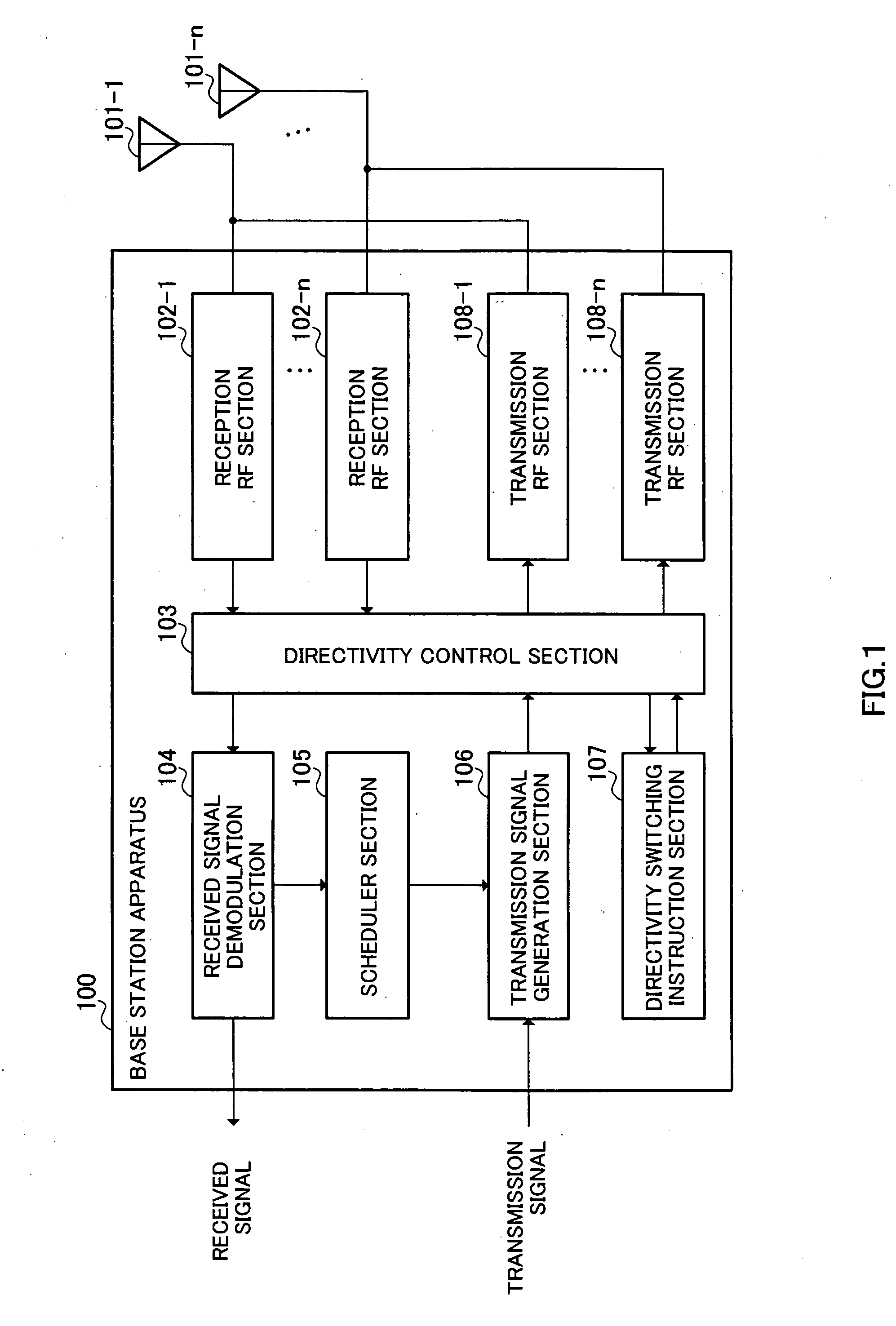
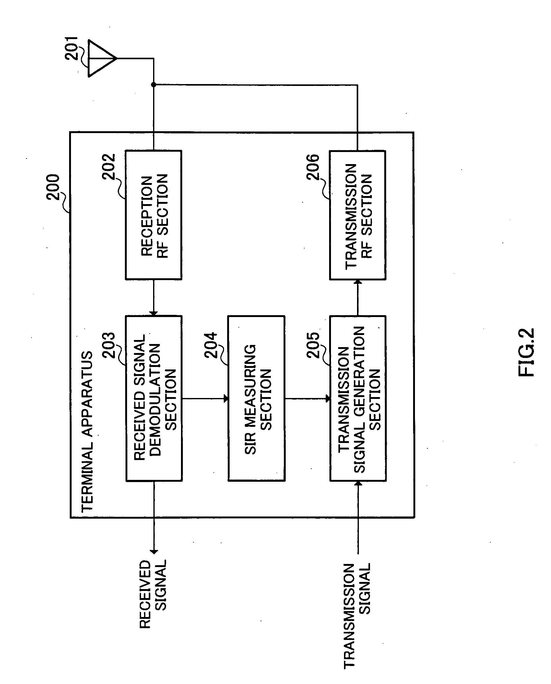
[0025]FIG. 1 illustrates the configuration of a base station apparatus according to Embodiment 1 of the present invention, FIG. 2 illustrates the configuration of a communication terminal apparatus according to Embodiment 1 of the present invention and FIG. 3 illustrates the configuration of a directivity switching instruction section according to Embodiment 1 of the present invention.

[0026] The base station apparatus 100 is mainly constructed of antenna elements 101-1 to 101-n, reception RF sections 102-1 to 102-n, a directivity control section 103, a received signal demodulation section 104, a scheduler section 105, a transmission signal generation section 106, a directivity switching instruction section 107 and transmission RF sections 108-1 to 108-n.

[0027] Furthermore, the terminal apparatus 200 is mainly constructed of an antenna element 201, a reception RF section 202, a received signal demodulation section 203, an SIR measuring section 204, a transmission signa...

Example

EMBODIMENT 2

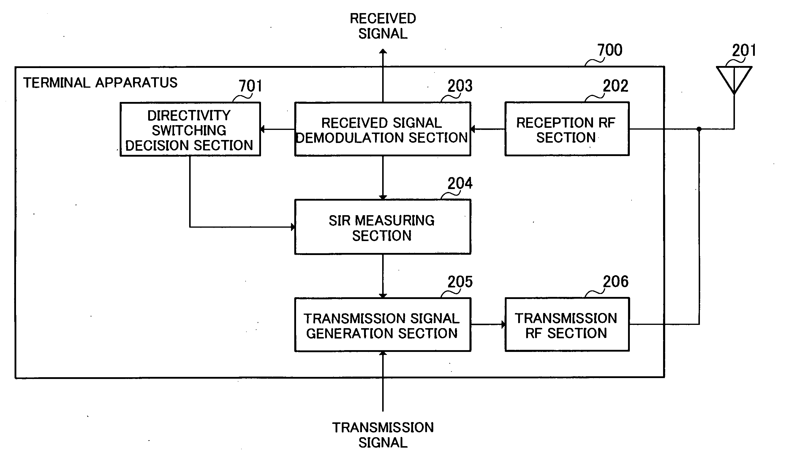
[0051]FIG. 6 illustrates the configuration of a base station apparatus according to Embodiment 2 of the present invention, FIG. 7 illustrates the configuration of a communication terminal apparatus according to Embodiment 2 of the present invention and FIG. 8 illustrates the configuration of a directivity switching instruction section according to Embodiment 2 of the present invention. This embodiment is characterized in that a base station apparatus notifies a terminal of a timing for switching between directivities. This embodiment differs in FIG. 6 from the embodiment in FIG. 1 in the configuration that a directivity switching signal generation section 601 is provided and differs in FIG. 7 from the embodiment in FIG. 2 in the configuration that a directivity switching decision section 701 is provided. The same components as those in FIG. 1 and FIG. 2 are assigned the same reference numerals and explanations thereof will be omitted.

[0052] A transmission signal genera...

Example

EMBODIMENT 3

[0065]FIG. 11 illustrates the configuration of a base station apparatus according to Embodiment 3 of the present invention, FIG. 12 illustrates the configuration of a terminal apparatus which is a communication terminal apparatus according to Embodiment 3 of the present invention, FIG. 13 illustrates the configuration of a directivity switching instruction section 1103 according to Embodiment 3 of the present invention and FIG. 14 illustrates the configuration of a directivity number information decision section according to Embodiment 3 of the present invention. This embodiment is characterized in that a base station apparatus notifies a terminal of directivity switching timings and directivity number information. This embodiment differs in FIG. 11 from the embodiment in FIG. 1 in that a directivity switching signal generation section 1101 and a directivity number information generation section 1102 are provided and differs in FIG. 12 from the embodiment in FIG. 2 in t...


PUM


Abstract

A directivity control section 103 performs weight control over a received signal using channel estimation and optimum weights, performs processing such as generation of the received signal and generates a plurality of weight-controlled transmission signals. A received signal demodulation section 104 extracts an SIR measurement result from the received signal. A scheduler section 105 decides which terminal should be assigned to a channel to be adaptively modulated from the SIR measurement result and at the same time decides the modulation multi-valued number and coding rate of the signal to the terminal. A transmission signal generation section 106 modulates a transmission signal such as a reference signal or packet data. A directivity switching instruction section 107 controls switching between directivities so as to maintain the same directivity after the reference signal is transmitted with a directivity until packet data is transmitted with a directivity. This makes it possible to receive packet data with high quality, improve efficiency of a radio frequency band and maximize communication path utilization efficiency.

Description

TECHNICAL FIELD [0001] The present invention relates to a base station apparatus and communication terminal apparatus, and more particularly, to a base station apparatus and communication terminal apparatus that transmit / receive packet data modulated and coded according to channel quality. BACKGROUND ART [0002] Conventionally, there is a scheme for a base station to use an adaptive array antenna and improve transmission quality through transmission with directivity. [0003] On the other hand, there is also a scheme called “adaptive modulation” in mobile communications under which a modulation / demodulation scheme is adaptively switched according to fluctuations in reception quality caused by fading. Setting an optimum modulation scheme according to a communication environment allows a large volume of packet data to be transmitted at high speed. [0004] When introducing a technology of an adaptive array antenna to a system carrying out adaptive modulation, a communication terminal appar...

Claims


Application Information

Patent Timeline
IPC IPC(8): H04B1/38H04B7/08H04B7/10H04B7/26H04L1/00H04W16/28
CPCH04B7/0604H04B7/0695H04L1/0003H04L1/0009H04W16/28
Inventor HOSHINO, MASAYUKIMIYOSHI, KENICHI
Owner GK BRIDGE 1
Why Eureka
Try Eureka