
Apparatus for and method of sampling and collecting powders flowing in a gas stream

a gas stream and apparatus technology, applied in the field of powder sampling, can solve the problems of difficult to handle and convey powders, and affecting the quality of powder samples, etc., and achieve the effect of high purity sampling

Inactive Publication Date: 2006-05-11
UMICORE AG & CO KG +1
View PDF99 Cites 103 Cited by
  • Summary
  • Abstract
  • Description
  • Claims
  • Application Information

AI Technical Summary

Benefits of technology

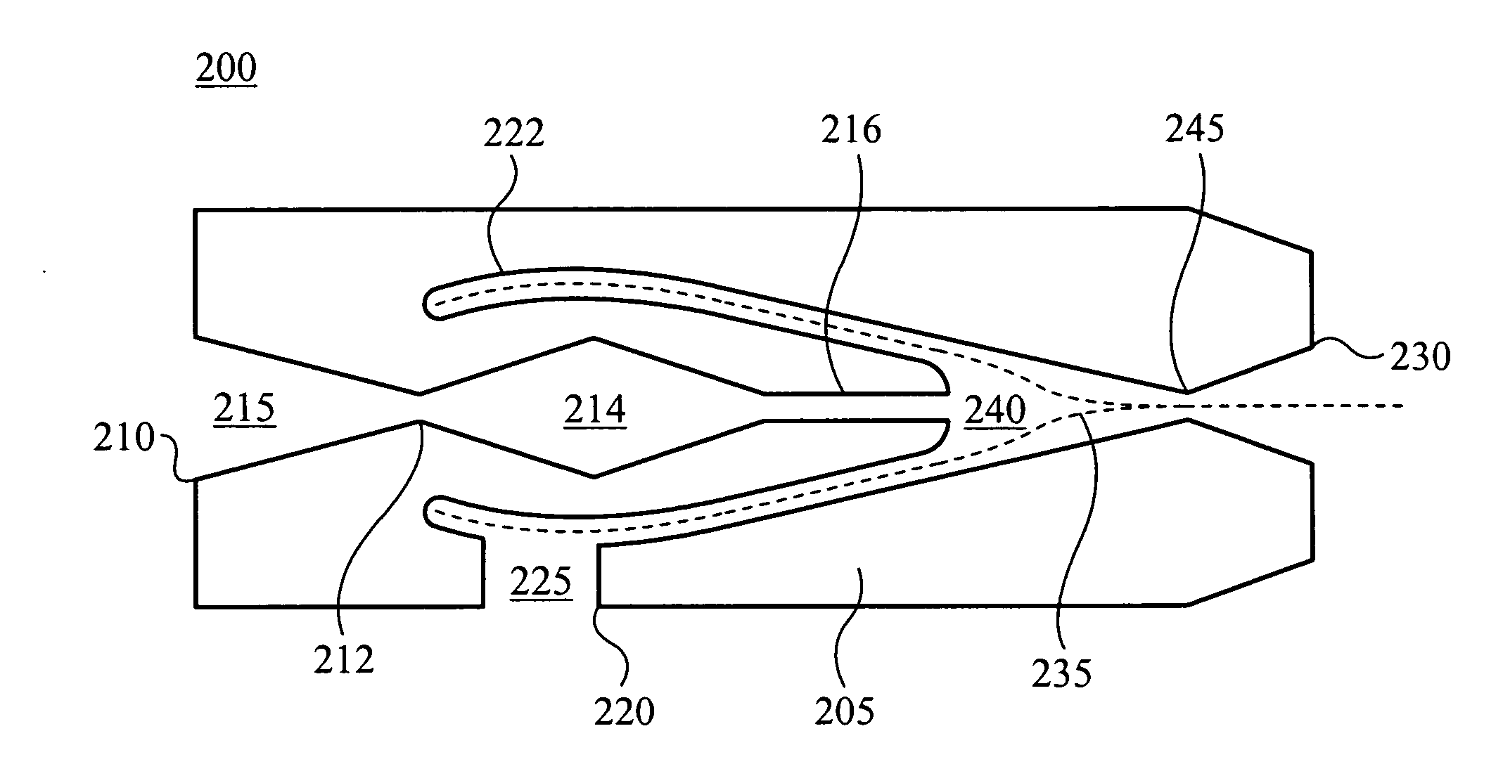
[0019] In the preferred application of the present invention, the process is repeated using additional mixtures, each of which can be unique. This repetition results in the collection of a plurality of high-purity samples of possibly unique materials, without cross-contamination among the samples. Further, in the preferred embodiment, the steps of ‘flowing a motive fluid’ and of ‘flowing a sweep gas’ are coordinated to maintain substantial entrainment of the first and the second target powders throughout the conduit network for the duration of the process. This coordination minimizes deposition of target powders within the conduit and the Venturi-type eductor used in the present invention.

Problems solved by technology

Traditional sampling methods are ill suited to the collection of vapor phase ultrafine particles.
Many powders possess properties that lead to agglomeration and clogging in small features and narrow apertures.
This generally such powders very difficult to handle and convey, and gives them a strong tendency to agglomerate with one another, and to adhere to surfaces and to small dimensions within mechanical devices.

Method used


Image

  • Apparatus for and method of sampling and collecting powders flowing in a gas stream
  • Apparatus for and method of sampling and collecting powders flowing in a gas stream
  • Apparatus for and method of sampling and collecting powders flowing in a gas stream

Examples


Embodiment Construction

[0025] The following description is presented to enable one of ordinary skill in the art to make and use the invention. Various modifications to the described embodiments will be readily apparent to those skilled in the art and the generic principles herein may be applied to other embodiments. Thus, the present invention is not intended to be limited to the embodiment shown but is to be accorded the widest scope consistent with the principles and features described herein.

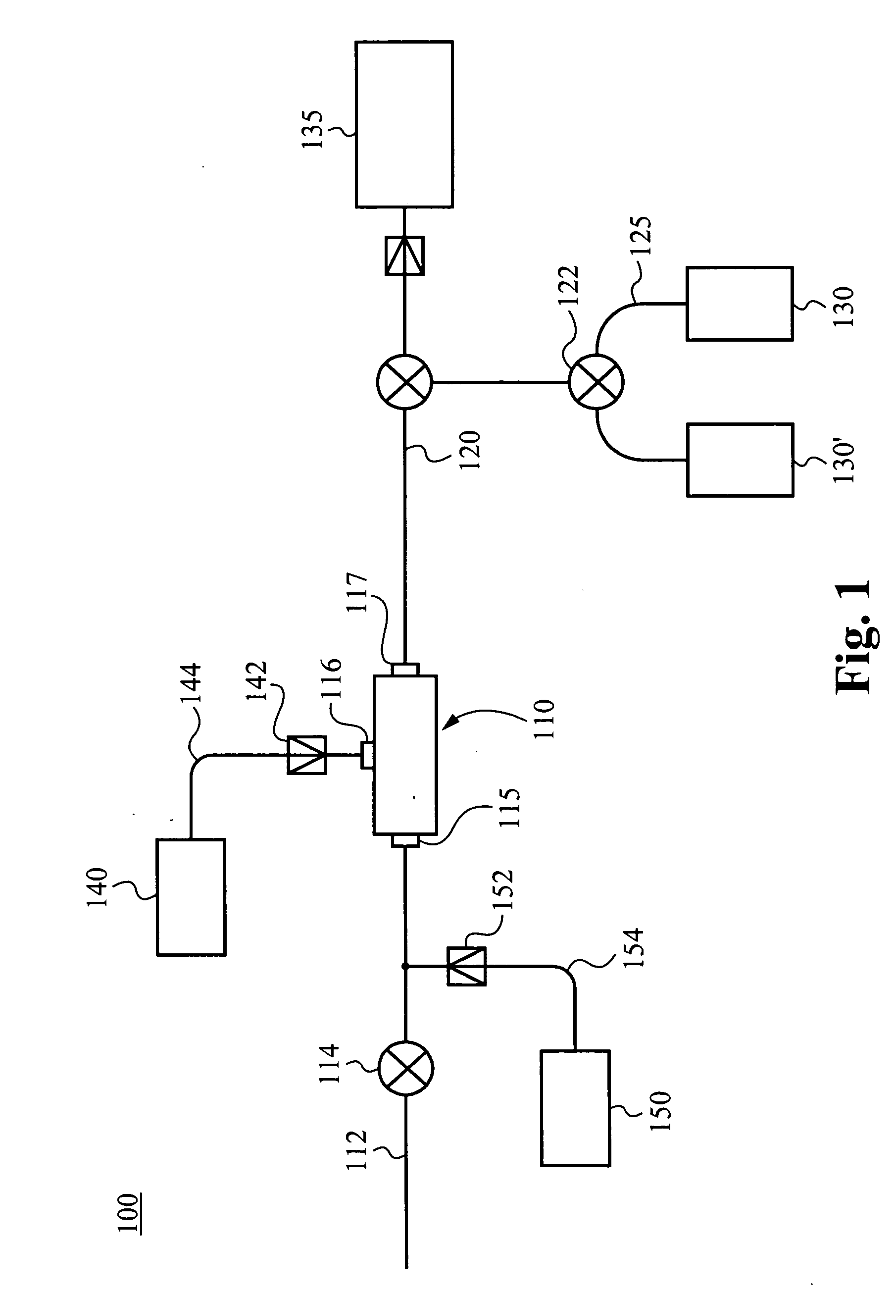
[0026] Referring now to FIG. 1, the apparatus 100 is illustrated. Generally, the apparatus 100 includes the suction generator 110, coupled through the conduit structure 120 with the collection elements 130 and 130′. The motive fluid reservoir 140 coupled with the suction generator 110, is one exemplary means of providing a motive fluid and suction generating power to the suction generator 110.

[0027] The suction generator 110 includes a suction inlet 115, a motive fluid inlet 116 and a outlet 117. As illustrated, ...


PUM

PropertyMeasurementUnit
Pressureaaaaaaaaaa

Abstract

A device for sampling of a mixture of ultrafine particles within a moving gas stream includes a suction generator, at least one sample collection element, and a conduit structure coupling the sample collection element with the suction generator. In some embodiments, the suction generator is configurable to separate by suction a portion of a gas stream containing a plurality of ultrafine particles, and to entrain with a motive fluid forming an output mixture. In some embodiments, a conduit is configured to accept a gas stream containing ultrafine particles and to channel it to the collection element.

Description

CROSS-REFERENCE TO RELATED APPLICATIONS [0001] This application claims priority under 35 U.S.C. §119(e) to co-pending U.S. Provisional Patent Application No. 60 / 617,586 filed Oct. 8, 2004, which is hereby incorporated by reference.FIELD OF THE INVENTION [0002] This invention relates to the field of powder sampling and more specifically a process of and apparatus for separating and collecting an ultrafine power from a flowing gas stream. BACKGROUND OF THE FIELD OF THE INVENTION [0003] Sampling particles from a gas stream presents several challenges. Traditional sampling methods are ill suited to the collection of vapor phase ultrafine particles. Many powders possess properties that lead to agglomeration and clogging in small features and narrow apertures. Due to their small size, ultrafine powders with effective diameters below 100 nanometers are subject to being acted upon by of even the slightest intermolecular forces. This generally such powders very difficult to handle and convey...

Claims


Application Information

Patent Timeline
IPC IPC(8): G01N1/22B01J19/00B01J19/08B22F9/28C12P21/06C23C16/00G01N1/20G01N15/00G01N33/00G01N33/53
CPCB01J19/0046B01J19/088B01J2219/00286B01J2219/00495B01J2219/00695B01J2219/00698B01J2219/00713B01J2219/00745B01J2219/00756B01J2219/0869B01J2219/0875B01J2219/0877B01J2219/0879B01J2219/0881B01J2219/0894B22F9/28G01N1/2035G01N1/2205G01N1/2247G01N2015/0096G01N2033/0091G01N33/0091
Inventor PESIRI, DAVID RICHARD
Owner UMICORE AG & CO KG
Learn More