Roll and printer

Inactive Publication Date: 2006-05-11
LINTEC CORP
View PDF7 Cites 21 Cited by
  • Summary
  • Abstract
  • Description
  • Claims
  • Application Information

AI Technical Summary

Benefits of technology

[0032] Further, adoption of a cutter blade capable of forming the projected portion in a part of peripheral edge of the label allows easy and swift operation of peeling off the release liner from the label.
[0033] Furthermore, such an arrangement is employed in the case where printing faults of the label base are detected, that the printing operation of the successive printing information is suspended and the repeated printing information is printed. Therefore, when the objects to be stuck with the label are conveyed corresponding to the printing sequence, it is no

Problems solved by technology

However, to employ such arrangement, a die cut roll or the like for forming a cut of a label shape is required at the downstream side of the sticking roll in addition to a sticking roll for sticking a protective film to the label base, which causes a disadvantage that a longer space is required for disposing components along a pay-out path and hence miniaturization of the apparatus is blocked.
Therefore, once a

Method used


Image

  • Roll and printer
  • Roll and printer
  • Roll and printer

Examples


first embodiment

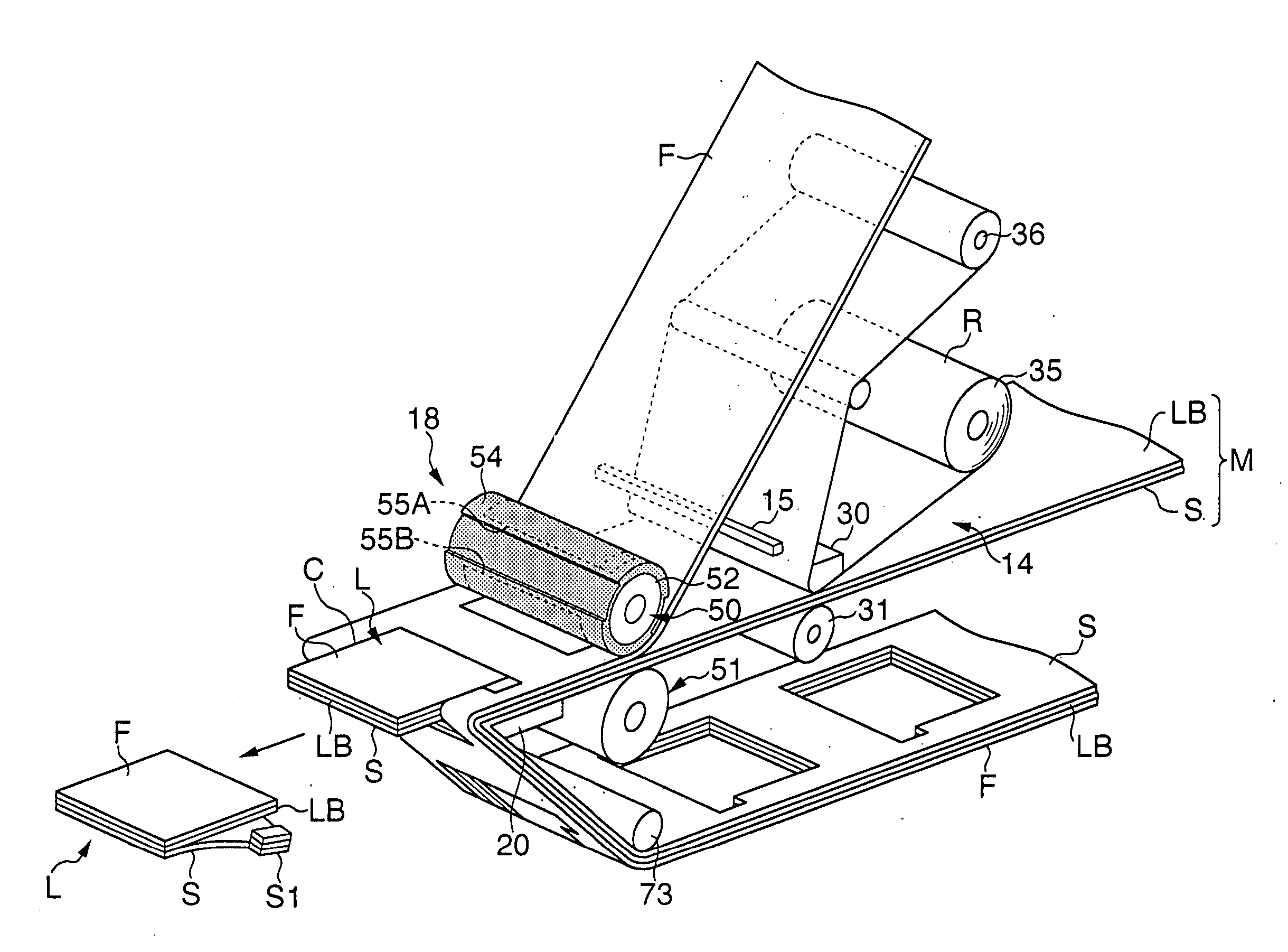
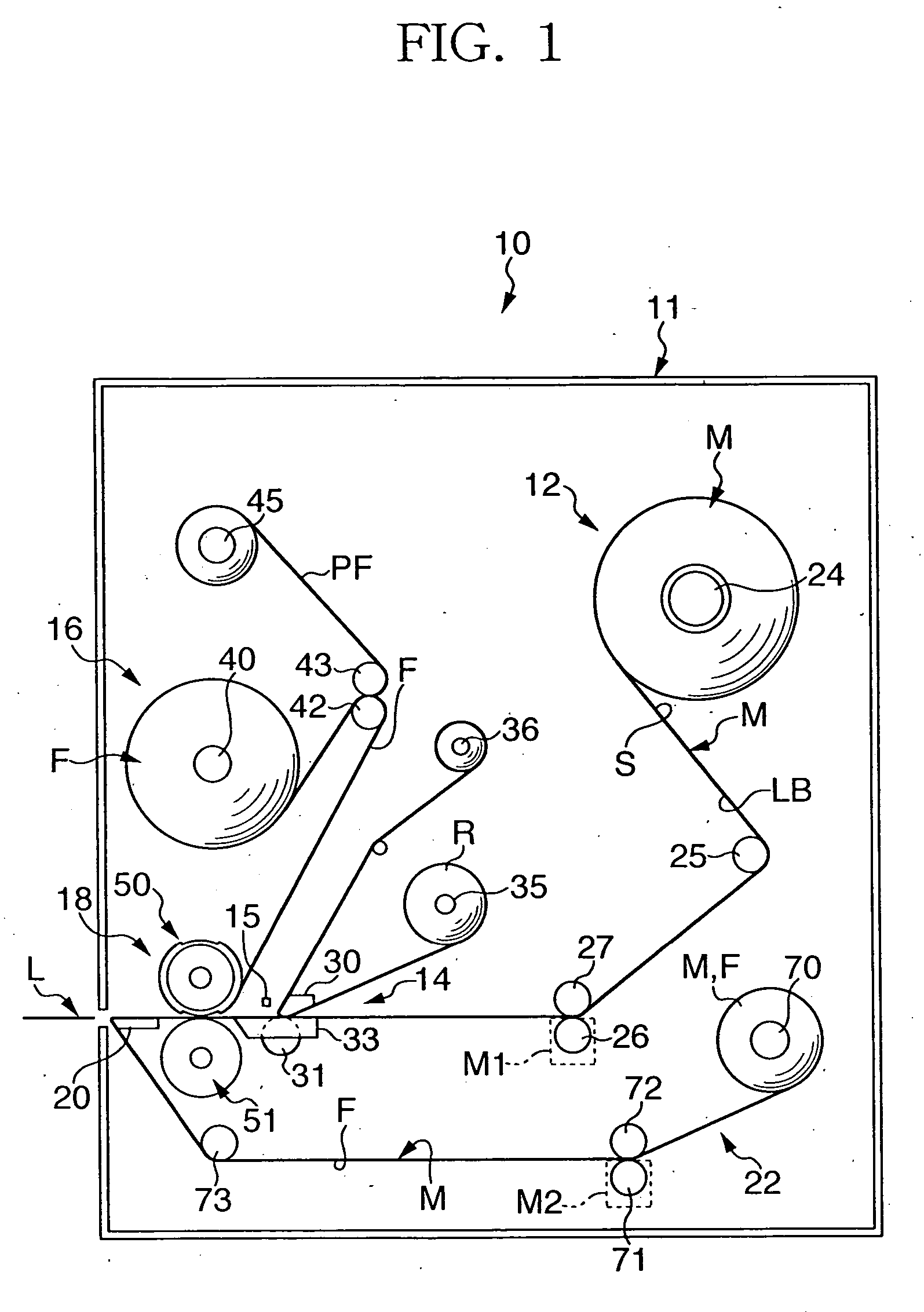
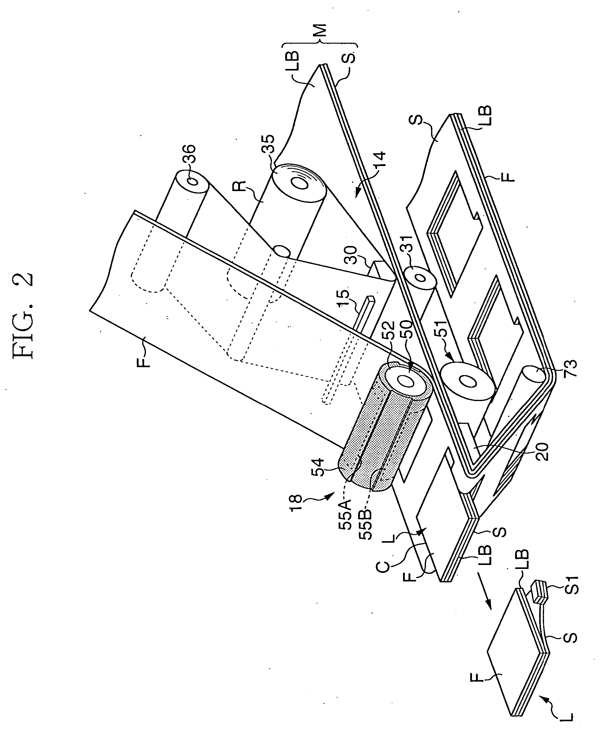
[0048]FIG. 1 is a schematic front view of a printer in accordance with a first -embodiment, and FIG. 2 is an enlarged perspective view schematically showing a principal portion thereof. Referring to the these drawings, a printer 10 is arranged to include a case 11, a pay-out section 12, which is provided in the case 11 to pay out a strip for label sheet M temporarily stuck with a label base LB on one surface of a release liner S, a printing section 14 for printing on the surface of the label base LB in process of paying out the label sheet M from the pay-out section 12, a sensor 15, which is disposed in the vicinity of the printing section 14 at the downstream side thereof to detect quality of printing, a film feeder 16 for supplying a strip of protective film F to the printed surface side of the label base LB, a sticking section 18 that sticks the protective film F to the label base LB and has a function to form a cut C (refer to FIG. 2) having a prescribed label shape, a plate mem...

second embodiment

[0066]FIG. 5 schematically shows a front view of a printer 10 in accordance with a second embodiment of the invention. The second embodiment is characterized in that the printing on a label base LB can be carried out without using an ink ribbon. That is, in this embodiment, the label base LB is constituted of a thermo sensitive paper, and the printing is carried out by imparting heat of a prescribed pattern to the label base. LB using a printing head 30. Other arrangements are identical to those of the first embodiment.

[0067] According to the second embodiment as described above, since the ink ribbon is not used, the arrangement can be simplified by eliminating the rolls for paying out and winding the ribbon and also the operation of routing the ribbon can be eliminated. In the case of the thermo sensitive paper, the legibility of the printed surface may be lost due to a heat caused by rubbing for some reason on the surface. However, in this embodiment, since the protective film F ...

third embodiment

[0068]FIG. 6 shows a third embodiment in accordance with the invention. This embodiment employs a protective film F without release liner PF on the rear surface thereof. Owing to this, the running cost can be reduced for no release liner PF on the protective film F exists, and in addition the apparatus can be compacted because there is no film winding roll 45. Other arrangements are identical to those of the first embodiment.


PUM

PropertyMeasurementUnit
Currentaaaaaaaaaa
Digital informationaaaaaaaaaa
Areaaaaaaaaaaa

Abstract

A printer 10 is arranged to include a pay-out section 12 for a strip of label sheet M having label base LB, a printing section 14 for printing on the surface of the label base LB, a film feeder 16 for supplying a protective film F and a sticking section 18 for sticking the protective film F to the label base LB. The sticking section 18 comprises a press roll 50 and a platen roll 51, the press roll 50 is arranged to include a soft member 54 on the peripheral portion of the roll body 52 and cutter blades 55A, 55B. The sticking section 18 sticks the protective film F as well as forms a cut C in the label sheet M and the protective film F corresponding to the configuration of the label L.

Description

BACKGROUND OF THE INVENTION [0001] 1. Field of the Invention [0002] The present invention relates to a roll and a printer, particularly to a roll, which is suitable for performing printing on a strip for label base temporarily stuck on a release liner, sticking a strip of protective film onto the printed surface and forming a cut having a label shape, and a printer capable of obtaining labels one by one using the roll. [0003] 2. Description of the Related Art [0004] Patent document 1 (Japanese Patent Application Laid-Open No. 2000-103420) discloses a printer capable of printing on the surface of a label. This printer employs the following arrangement; i.e., using a label sheet in which labels previously formed into a label shape are temporarily stuck at prescribed intervals on one surface of a strip of release liner, a printing is carried out in process of paying but the label sheet. The following arrangement is also employed; i.e., a film formed in an appropriate size to protect th...

Claims


Application Information

Patent Timeline
IPC IPC(8): B32B37/00B65C11/02B31D1/02B65C9/18B65C9/40
CPCB31D1/021B65C9/1826B65C11/0289B65C2009/405B65C2210/007B26F1/384B32B38/0004B32B7/06B32B2519/00
Inventor TSUKAMOTO, KATSUHIDEHIRASE, HIROSHI
Owner LINTEC CORP
Why Eureka
Try Eureka