Method and system for dispensing liquid from a module having a flexible bellows seal

a flexible bellows seal and liquid technology, applied in the field of methods and systems, can solve the problems of increased requirements, friction and seal wear, undesired dispensing discontinuities, etc., and achieve the effect of enhancing the securement of the seal to the needle guide and enhancing the securement of the seal to the needl

Active Publication Date: 2006-05-11
NORDSON CORP
View PDF32 Cites 31 Cited by
  • Summary
  • Abstract
  • Description
  • Claims
  • Application Information

AI Technical Summary

Benefits of technology

[0007] The dispensing module further includes a needle guide mounted to the dispenser body and includes a passage for receiving a portion of the needle. The needle moves relative to the needle guide between the open and closed positions. To prevent liquid from leaking out of the flow channel, the module includes a flexible seal having a first and second end with the first end coupled to the needle guide and the second end coupled to the needle. The second end is adapted to move with the needle as it reciprocates. The module also includes an actuator that is operatively coupled to the needle and capable of actuating the needle between the open and closed positions to selectively dispense liquid from the discharge outlet.
[0008] In one exemplary embodiment, the seal includes a seal body having a top portion, a central portion, and a bottom portion. There is a first opening in the top portion, a second opening in the bottom portion and a passageway extending between the first and second openings. The firs...

Problems solved by technology

These dynamic seals may press tightly against the valve stem and cause friction and seal wear.
The higher friction may place greater demands on the requirements for pressurized air to move the valve stem.
On the other hand, selecting a looser dynamic seal could resul...

Method used


Image

  • Method and system for dispensing liquid from a module having a flexible bellows seal
  • Method and system for dispensing liquid from a module having a flexible bellows seal
  • Method and system for dispensing liquid from a module having a flexible bellows seal

Examples


Embodiment Construction

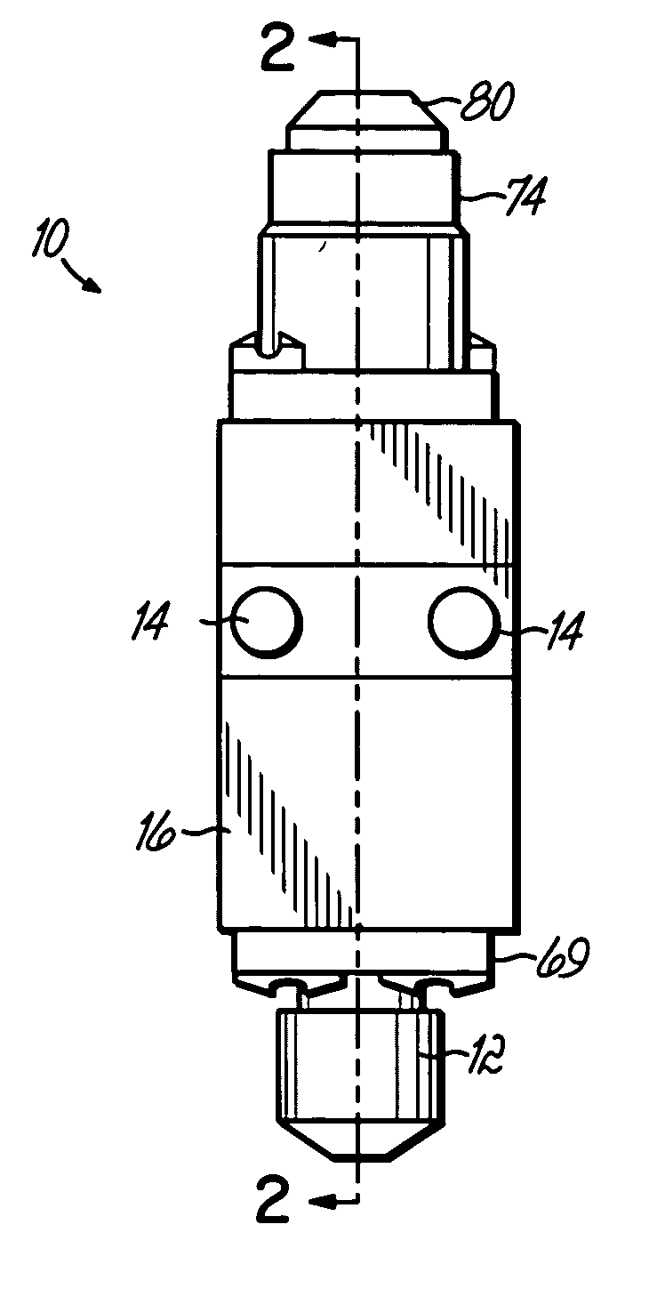
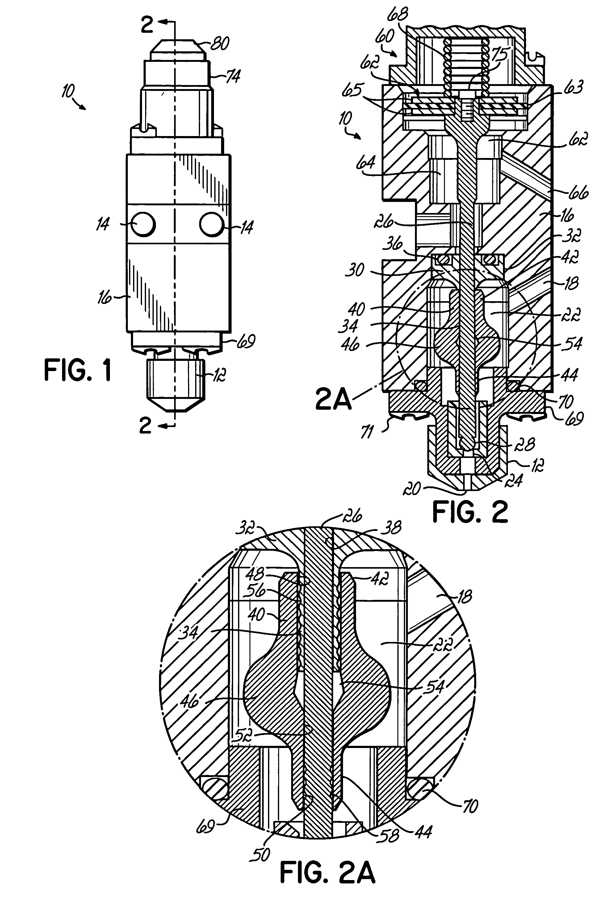
[0016]FIG. 1 depicts an exemplary dispensing module 10 in accordance with the principles of the present invention. The exterior appearance of the module 10 resembles a convention dispensing module in that it includes a dispensing nozzle 12 from which adhesive or other liquid is dispensed and includes bolts, or other fasteners 14 for connecting the module 10 to a gun manifold, or body (not shown). FIG. 2 provides a cut-away view of the module 10 and more clearly shows the needle, seals and other components within the module 10 that operate to dispense liquid from the dispensing nozzle 12 in a controlled manner.

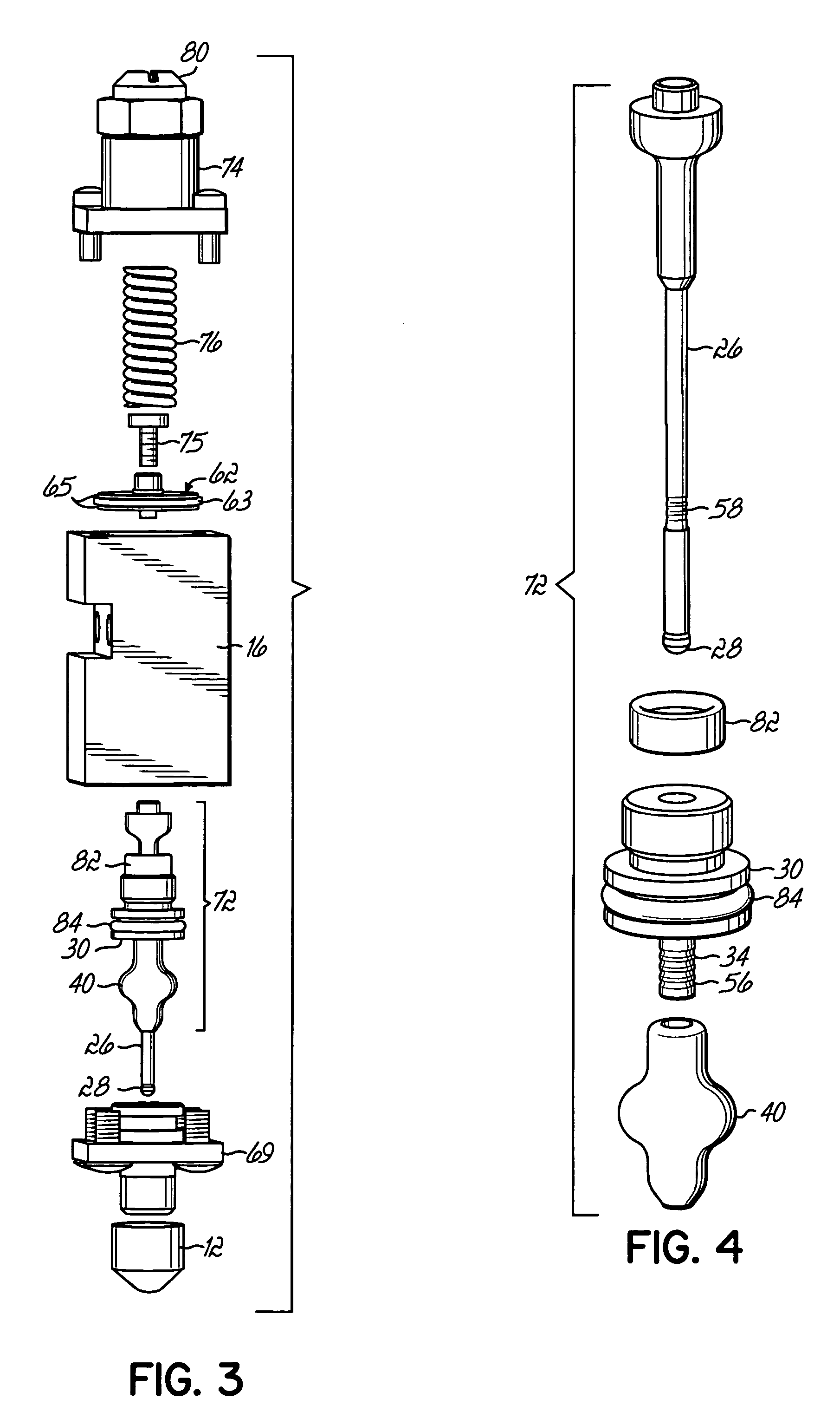
[0017] With reference to FIG. 2, the module 10 typically includes a dispenser body 16 having a liquid inlet 18, a discharge outlet 20, and a flow channel 22 between the liquid inlet 18 and the discharge outlet 20 capable of directing a flow of the liquid. The flow channel 22 includes a valve seat 24 near the discharge outlet 20. A valve stem or needle 26 is mounted in dispense...


PUM

PropertyMeasurementUnit
Flexibilityaaaaaaaaaa

Abstract

A dispensing module for dispensing liquid includes a dispensing body having an inlet, a discharge outlet, and a flow channel therebetween having a valve seat. A needle having a valve element is mounted to the body and reciprocates therein between an open position, in which the valve element is disengaged from the valve seat thereby allowing liquid flow, and a closed position, in which the valve element is engaged with the valve seat thereby preventing liquid flow. A needle guide is mounted to the dispenser body and includes a passage for receiving a portion of the needle. A flexible seal includes a first end coupled to the needle guide and a second end coupled to the needle and moving therewith. An actuator is operatively coupled to the needle and moves the needle between the open and closed positions. The seal includes a central portion with an interior cavity that stretches and compresses as the needle reciprocates.

Description

FIELD OF THE INVENTION [0001] This invention generally relates to liquid dispensing devices used for a variety of purposes, but particularly useful for viscous liquids such as hot melt adhesives, sealing compounds, paints, etc. Such devices are referred to as fluid control valves or dispensing guns or modules. BACKGROUND OF THE INVENTION [0002] A typical dispensing device for supplying liquid, such as hot melt adhesive, generally includes a body having a valve stem that opens and closes a dispensing orifice. The valve stem is usually actuated in at least one direction by pressurized air to dispense discrete amounts of pressurized liquid. Either a spring mechanism or pressurized air is used to move the valve stem in an opposite direction against a valve seat. This stops the flow of liquid from the dispensing orifice. [0003] More specifically, devices generally related to the present invention include a liquid passage adjacent the dispensing orifice and an actuator cavity or chamber a...

Claims


Application Information

Patent Timeline
IPC IPC(8): B67D3/00
CPCB05C5/0225
Inventor RINEY, JOHN M.
Owner NORDSON CORP
Why Eureka
Try Eureka