Method and arrangement for operating a magnetically levitated vehicle

a magnetically levitation, vehicle technology, applied in the direction of motor/generator/converter stopper, dynamo-electric converter control, etc., can solve the problems of considerable increase in the cost of installation, which is not in any way acceptable, and the effect of increasing the cost of installation

Inactive Publication Date: 2006-05-11
SIEMENS AG
View PDF16 Cites 22 Cited by
  • Summary
  • Abstract
  • Description
  • Claims
  • Application Information

AI Technical Summary

Benefits of technology

[0005] Starting from the above it is an object of the invention to make it possible, with methods and arrangements specified above, to at least halve the time intervals with which the vehicles can follow along the track.

Problems solved by technology

This is not in any way acceptable in view of the considerable increase in the cost of installation that it involves and the fact that a need for special unscheduled journeys generally only exists for a certain time, i.e. at given times of day or when there are unforeseen traffic conditions.

Method used


Image

  • Method and arrangement for operating a magnetically levitated vehicle
  • Method and arrangement for operating a magnetically levitated vehicle
  • Method and arrangement for operating a magnetically levitated vehicle

Examples


Embodiment Construction

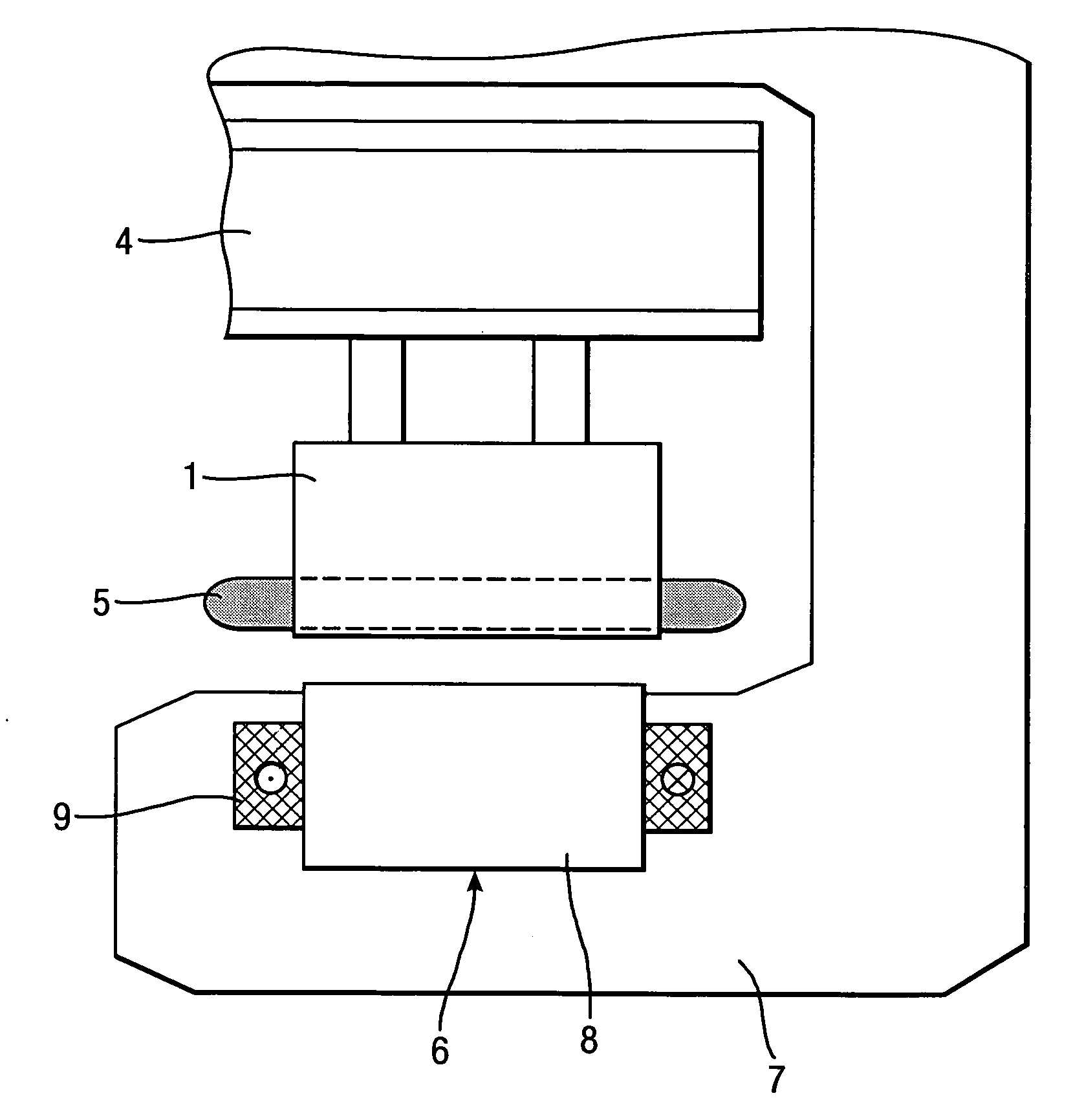
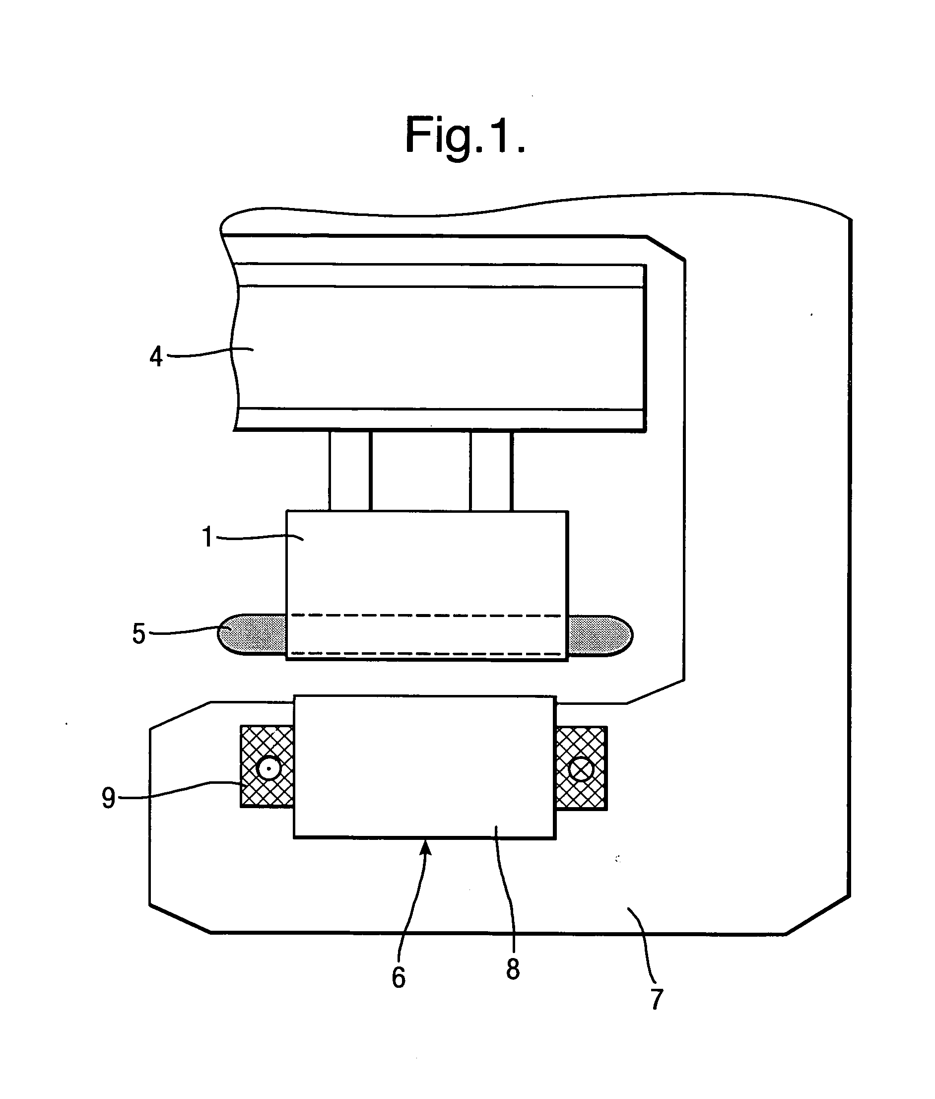
[0017] On a magnetically levitated railway having a synchronous long-stator linear motor (FIGS. 1 and 2), a laminated stator core 1, which has a plurality of slots and teeth arranged in succession to one another, is connected in a fixed position to a track 4 which is set up along a preset route. Inserted in the slots in the laminated stator core 1 is a long-stator winding 5 in the form of a three-phase winding which is fed with three-phase current of variable amplitude and frequency by a converter, as a result of which an advancing travelling (transient) wave is set up in a known fashion longitudinally of the long-stator linear motor. The exciter field of the long-stator linear motor is generated by an exciter arrangement 6 which is formed by a plurality of magnets which are mounted on a vehicle 7, which are arranged in a distributed fashion in the latter's longitudinal direction, which at the same time perform a supporting function and which each comprise a magnet core 8 and an exc...


PUM


Abstract

The invention relates to a method and an arrangement for operating a magnetically levitated vehicle by means of an arrangement having at least one long-stator linear motor. The linear motors are sub-divided longitudinally of a track into individual motor regions (A3, A4) in which only one vehicle (7e, 7f) at a time can normally travel. To increase the vehicle concentration along the track, provision is made in accordance with the invention for selected motor regions (A4) to be divided into at least two mutually independent motor region sections (A4a, A4b) and for one vehicle (7f, 7g) to be operated in each motor region section (A4a, A4b) at a part of that power which is preset for each motor region (A4).

Description

FIELD OF THE INVENTION [0001] The invention relates to a method and an arrangement for operating a magnetically levitated vehicle which arrangement has at least one a.c. winding which is laid out longitudinally of a track and is sub-divided into winding sections, an exciter arrangement which is mounted on the vehicle, track-segment cables arranged longitudinally of the track and voltage sources assigned to the track-segment cables, the winding sections being connected to assigned track-segment cables and voltage sources in line with the movement of the vehicle, wherein the track-segment cables, the winding sections and the voltage sources are so assigned to motor regions which follow one another along the track that, under normal operating conditions, one vehicle is operated in each motor region at a power which is preset for the motor region and is supplied by the assigned voltage sources. BACKGROUND OF THE INVENTION [0002] In known methods and arrangements of this kind, use is mad...

Claims


Application Information

Patent Timeline
Patent Type & Authority Applications(United States)
IPC IPC(8): E01B7/10H02K41/00
CPCB60L13/10B60L2200/26B60M3/04
Inventor FISCHPERER, ROLF
Owner SIEMENS AG
Why Eureka
Try Eureka