Eureka AIR delivers breakthrough ideas for toughest innovation challenges, trusted by R&D personnel around the world.

Folding bicycle

a folding bicycle and bicycle technology, applied in the field of folding bicycles, can solve the problems of excessively large size, difficulty in carrying the bicycle in a train, bus, or other directions, and achieve the effects of small size, high portability, and excessive large siz

Inactive Publication Date: 2006-05-11
KOBAYASHI JOUJI
View PDF13 Cites 38 Cited by
  • Summary
  • Abstract
  • Description
  • Claims
  • Application Information

AI Technical Summary

Benefits of technology

[0003] Conventional folding bicycles have an excessively large size even in the state wherein the bicycle is folded, leading to difficulty in the user carrying the bicycle in a train, bus, or the like. Furthermore, the conventional folding bicycles have a problem of excessively large weight, leading to difficulty in carrying thereof. It is an object of the present invention to provide a highly portable folding bicycle with a small size and small weight, which allows the user to carry the bicycle with ease in mass transit means such as a train, bus, and so forth.
[0007] Furthermore, a universal joint is included at the lower portion of the handle support such that the handle support has an inclination as to an axis extending along the lateral direction, and passing through the middle portion of the universal joint, as an tilted axis, so as to extend backwards, thereby improving ease-of-use of steering. Furthermore, an arrangement may be made wherein a pair of front wheels is disposed in parallel at the end of a lower shaft of the universal joint, with the lower shaft being engaged with a head tube with an inclination of a suitable angle as to an axis passing through a middle portion of the universal joint and extending along the lateral direction as a tilted axis, so as to extend backward.
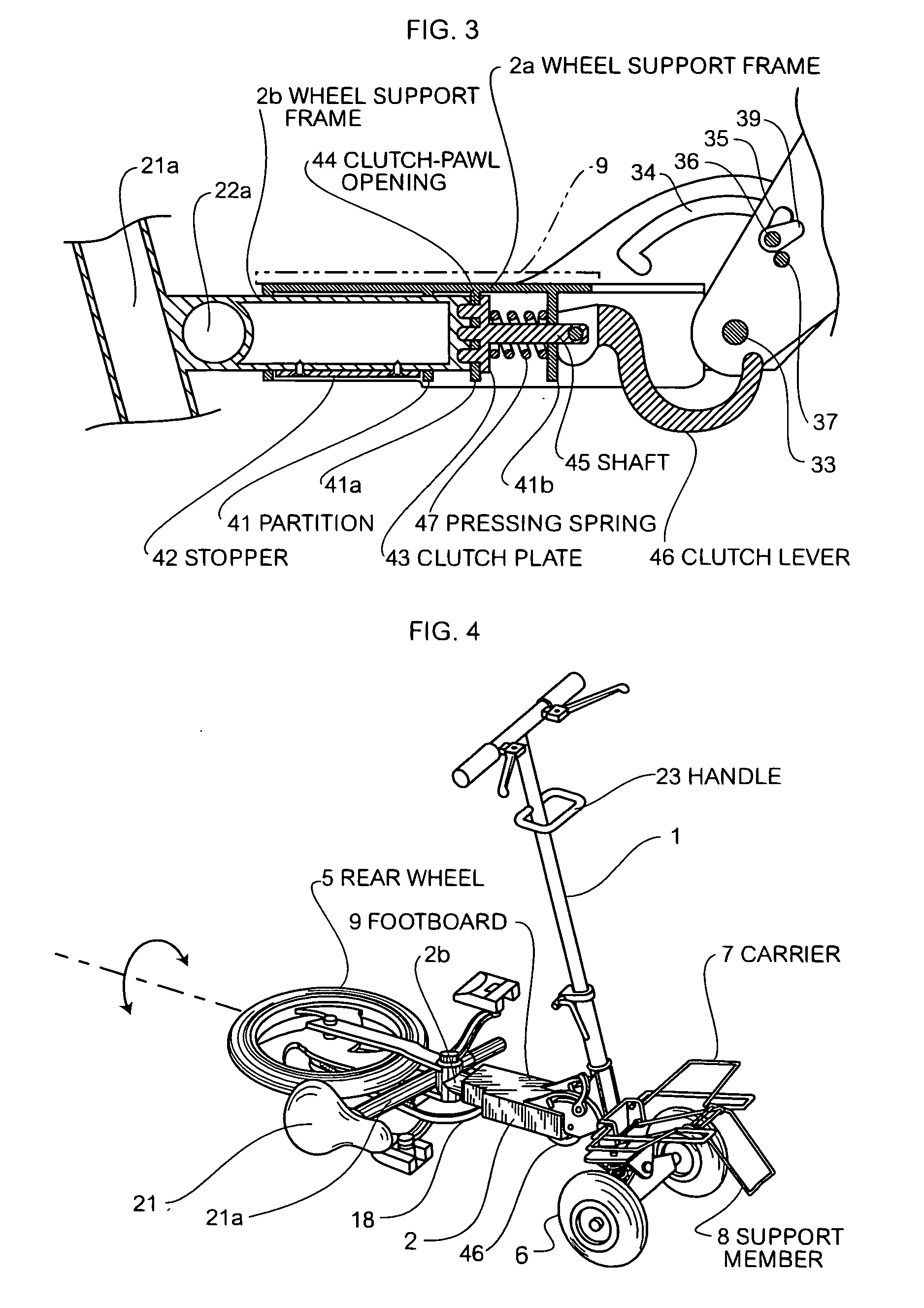
[0008] The folding bicycle having such a configuration described above allows the user to switch from the upright state to the flat state wherein the rear wheel is turned by 90° with the wheel support frame as a turning axis extending along the longitudinal direction by actions of the folding mechanism and the connection mechanism. Furthermore, such a configuration allows the user to fold the rear wheel side toward the handlebars, so as to achieve the upright state of the rear wheel and the handlebars. This reduces storage volume of the bicycle, i.e., enables folding down to a small storage size.
[0009] Furthermore, the folding bicycle, having a configuration wherein the front wheels are disposed in parallel at the lower portion of the handle support, allows the user to stably carry the bicycle in the folded state by gripping and pulling the upper portion of the handle. Furthermore, the folding bicycle having a configuration wherein the carrier is disposed at a somewhat upper portion of the lower portion of the handle support, allows the user to use the bicycle as a cart, as well as serving as a carrier of the bicycle during cycling. Furthermore, with the folding bicycle having a configuration wherein the carrier including the support member having a function which allows the user to switch between the turnable state and the fixed state, the bicycle folded in the storage state can be supported by the front wheels thus disposed in parallel and the aforementioned support member, thereby allowing the folded bicycle to stably stand on the ground by itself.
[0010] Furthermore, the folding bicycle including the footboard on the wheel support frame allows the user to place one foot on the footboard.

Problems solved by technology

Conventional folding bicycles have an excessively large size even in the state wherein the bicycle is folded, leading to difficulty in the user carrying the bicycle in a train, bus, or the like.
Furthermore, the conventional folding bicycles have a problem of excessively large weight, leading to difficulty in carrying thereof.

Method used


Image

  • Folding bicycle
  • Folding bicycle
  • Folding bicycle

Examples


Embodiment Construction

[0065] Description will be made regarding embodiments according to the present invention with reference to the drawings.

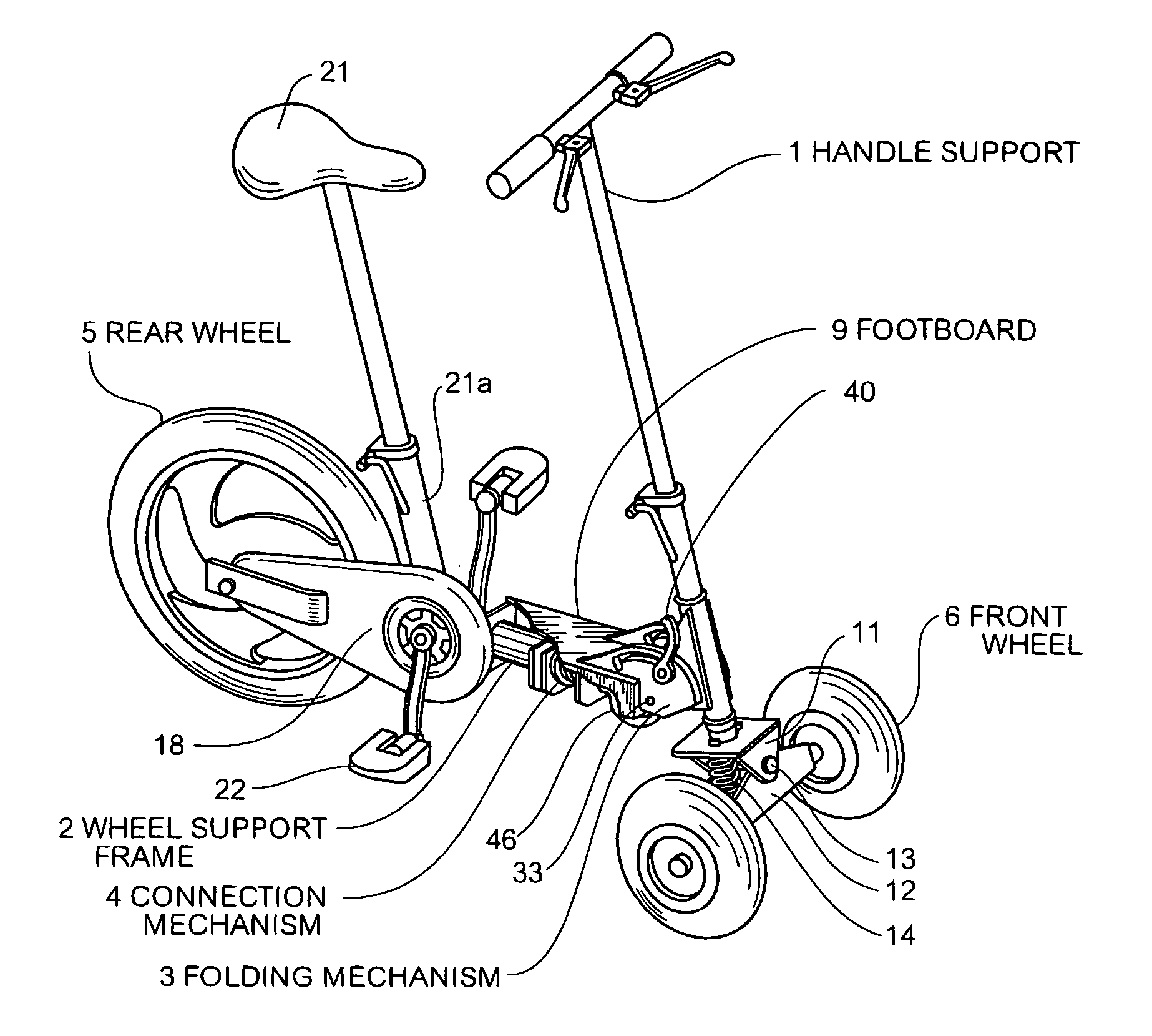
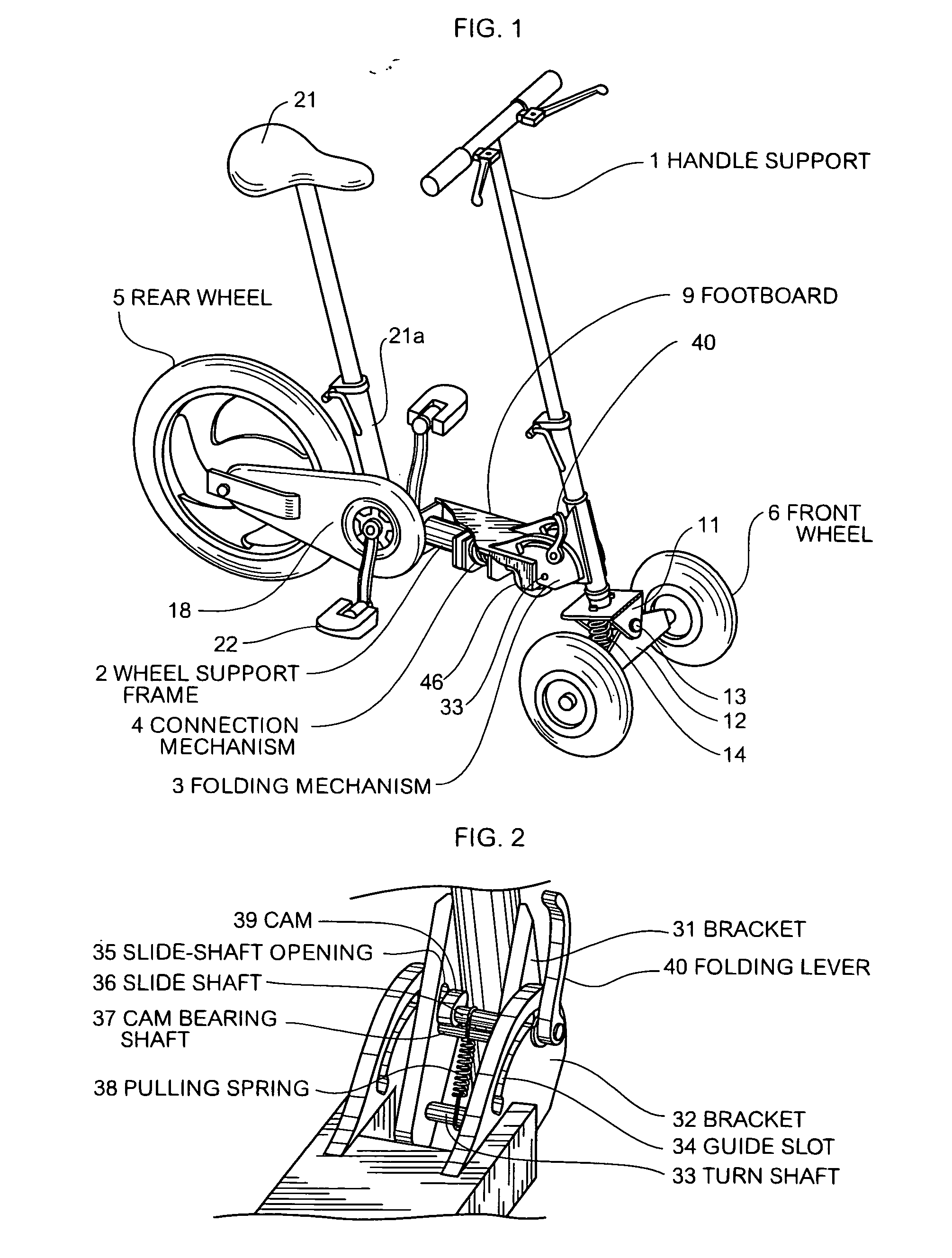
[0066] As shown in FIG. 1, a folding bicycle according to an embodiment of the present invention has a configuration wherein a handle support 1 is engaged with a wheel support frame 2 through a folding mechanism 3 which allows switching between a fixed state and a turnable state. Furthermore, a connection mechanism 4 is provided for the aforementioned wheel support frame 2, thereby allowing switching between the fixing state wherein a rear wheel 5 is fixed and the turnable state which allows the user to turn the rear wheel 5 with the aforementioned wheel support frame 2 as a turning axis.

[0067] The lower portion of the handle support 1 is fixed to a metal member 11 having a U-shaped cross-section. Furthermore, another metal member 12 having a U-shaped cross-section is engaged with the metal member 11 having a U-shaped cross-section so as to face one another. Furt...


PUM


Abstract

[Object] To provide a portable folding bicycle which allows the user to carry the bicycle with ease in a train, bus, or the like, without any trouble. [Solving Means] A handle support 1 and a wheel support frame 2 are engaged with each other through a folding mechanism 3 which allows the user to turn the handle support 1 and the wheel support frame 2 around the turning axis extending along the lateral direction. Furthermore, the wheel support frame 2 includes a connection mechanism 4 which can be turned on a turning axis extending the longitudinal direction, thereby allowing connection of a rear wheel to the wheel support frame 2 while allowing switching between the turnable state, which allows the user to turn the rear wheel with the wheel support frame 2 as a turning axis, and the fixed state.

Description

TECHNICAL FIELD [0001] The present invention relates to a carriable folding bicycle with excellent mobility. BACKGROUND ART [0002] Conventional folding bicycles have a hinging portion around the middle portion of a frame for connecting a front wheel and a rear wheel, which allows folding of the bicycle (see Japanese Unexamined Patent Application Publication No. 2001-130471, for example). At the time of carrying the bicycle thus folded, the folded bicycle is packed in a bag. DISCLOSURE OF THE INVENTION [0003] Conventional folding bicycles have an excessively large size even in the state wherein the bicycle is folded, leading to difficulty in the user carrying the bicycle in a train, bus, or the like. Furthermore, the conventional folding bicycles have a problem of excessively large weight, leading to difficulty in carrying thereof. It is an object of the present invention to provide a highly portable folding bicycle with a small size and small weight, which allows the user to carry t...

Claims


Application Information

Patent Timeline
Patent Type & Authority Applications(United States)
IPC IPC(8): B62K15/00B62K5/02B62K5/05B62K5/06
CPCB62K5/05B62K15/00
Inventor KOBAYASHI, JOUJI
Owner KOBAYASHI JOUJI
Why Eureka
Eureka Blog
Learn More