Light source device and display device

Inactive Publication Date: 2006-05-11
FUJITSU LTD
View PDF11 Cites 0 Cited by
  • Summary
  • Abstract
  • Description
  • Claims
  • Application Information

AI Technical Summary

Benefits of technology

[0005] The object of the present invention is to provide a light so

Problems solved by technology

Usually, a sufficient amount of mercury gas is sealed in the discharge tube to enable the discharg

Method used


Image

  • Light source device and display device
  • Light source device and display device
  • Light source device and display device

Examples


Embodiment Construction

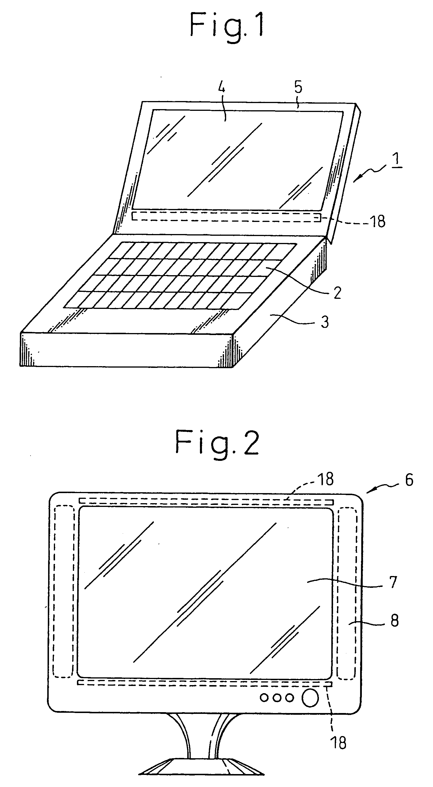
[0034] Embodiments of the present invention will be explained hereinafter with reference to the accompanying drawings. FIG. 1 is a view showing the notebook type personal computer including the light source device according to the embodiment of the present invention, and FIG. 2 is a view showing the display device including the light source device according to the present invention.

[0035] In FIG. 1, the notebook type personal computer 1 comprises a body 3 having a keyboard 2 and electronic circuits, and a display part 5 having a display 4 such as a liquid crystal display device. The display part 5 has a light source device 18. The notebook type personal computer 1 of FIG. 1 includes one light source device 18, but it is possible to arrange two light source devices 18, as in the case of the display device 6 of FIG. 2.

[0036] In FIG. 2, the display device 6 comprises a body 8 having a display 7 such as a liquid crystal display device and electronic circuits. The body 8 has light sour...


PUM


Abstract

A light source device includes a discharge tube, a reflector for reflecting a light radiated from the discharge tube, and support members for supporting the discharge tube to the reflector. The support member or the discharge tube is formed of a heat insulating structure so as to prevent a temperature drop of a portion of the discharge tube near electrodes thereof. By this arrangement, it is possible to prolong the operational life of the discharge tube.

Description

[0001] This application is a continuation of application Ser. No. 10 / 663,708, filed on Sep. 17, 2003, which is a continuation of PCT / JP 02 / 02622 filed Mar. 19, 2002, which claims the priority of Japanese Application No. 2001-078546 filed Mar. 19, 2001, which is incorporated herein by reference.TECHNICAL FIELD [0002] The present invention relates to a light source device having a discharge tube emitting light by a discharge in a lean gas. BACKGROUND ART [0003] A backlight, as a light source device of a display device such as a liquid crystal display device, uses a light source device comprising one or a plurality of discharge tubes and a reflector. The discharge tube is a cold cathode tube, in which mercury is contained in a lean gas (such as Ar and Ne) and a fluorescent material is coated on the tube wall. Electrodes are provided in both ends of the discharge tube. The discharge tube is supported by the reflector with support members which are arranged at positions near the electrod...

Claims


Application Information

Patent Timeline
IPC IPC(8): H01J61/20H01J17/20F21S2/00F21V7/00F21V8/00F21V19/00F21V29/15F21V29/505F21Y101/00G02F1/13357H01J61/52H01J61/72
CPCF21V19/009F21V29/004G02F1/133604G02F1/133608F21V29/85H01J61/523H01J61/72F21V29/15G02F2001/133628G02F1/133628G02F1/1335
Inventor SOTOKAWA, AKIOHACHISUKA, SEIJI
Owner FUJITSU LTD
Why Eureka
Try Eureka