Rotation detecting device

a detection device and rotating technology, applied in the direction of magnetic measurement, speed/acceleration/shock measurement, instruments, etc., can solve the problem of major errors in the rotation data

Active Publication Date: 2006-05-11
DENSO CORP
View PDF4 Cites 43 Cited by
  • Summary
  • Abstract
  • Description
  • Claims
  • Application Information

AI Technical Summary

Benefits of technology

[0007] Therefore, an object of the invention is to provide an improved rotation detecting device having magnetic sensors that can be set at a more accurate distance from a rotary magnetic member.
[0008] Another object of the invention is to provide a rotation detecting device that is easy to correct detection errors.
[0013] Another object of the invention is to provide a rotation detecting device that can detect an accurate rotation state even if there is a variation in the distance between the rotor member and the semiconductor chip.

Problems solved by technology

In that common rotation detecting device, a variation in the distance between the magnetoresistance sensors and the rotor member causes one of major errors in the rotation data.
In this rotation detecting device, a similar problem is caused by a variation in the distance between the magnetoresistance sensors and the rotor member.

Method used


Image

  • Rotation detecting device
  • Rotation detecting device
  • Rotation detecting device

Examples


Embodiment Construction

[0032] A rotation detecting device according to the first embodiment of the invention will be described with reference to FIGS. 1-4 and FIGS. 5A-5F.

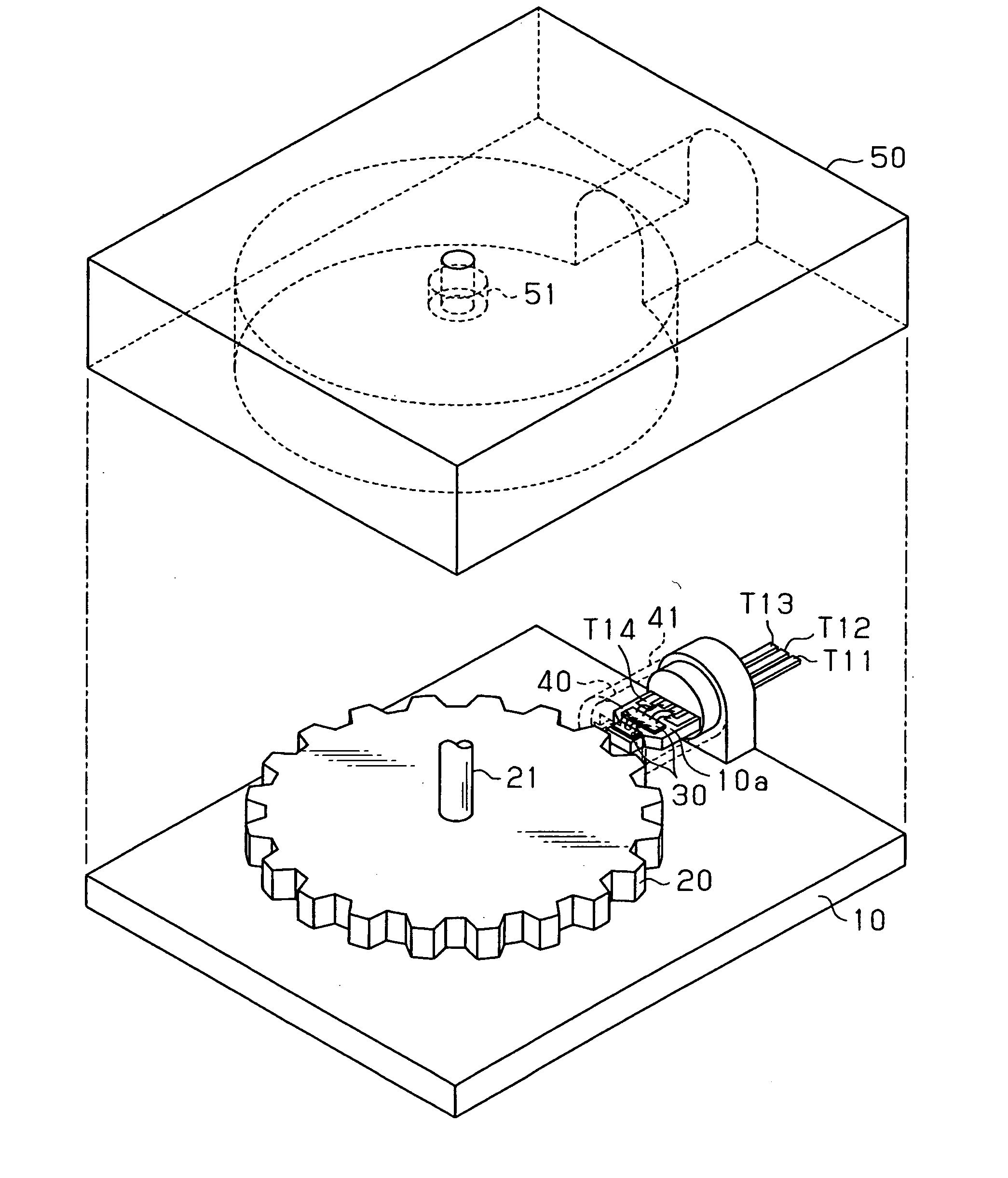
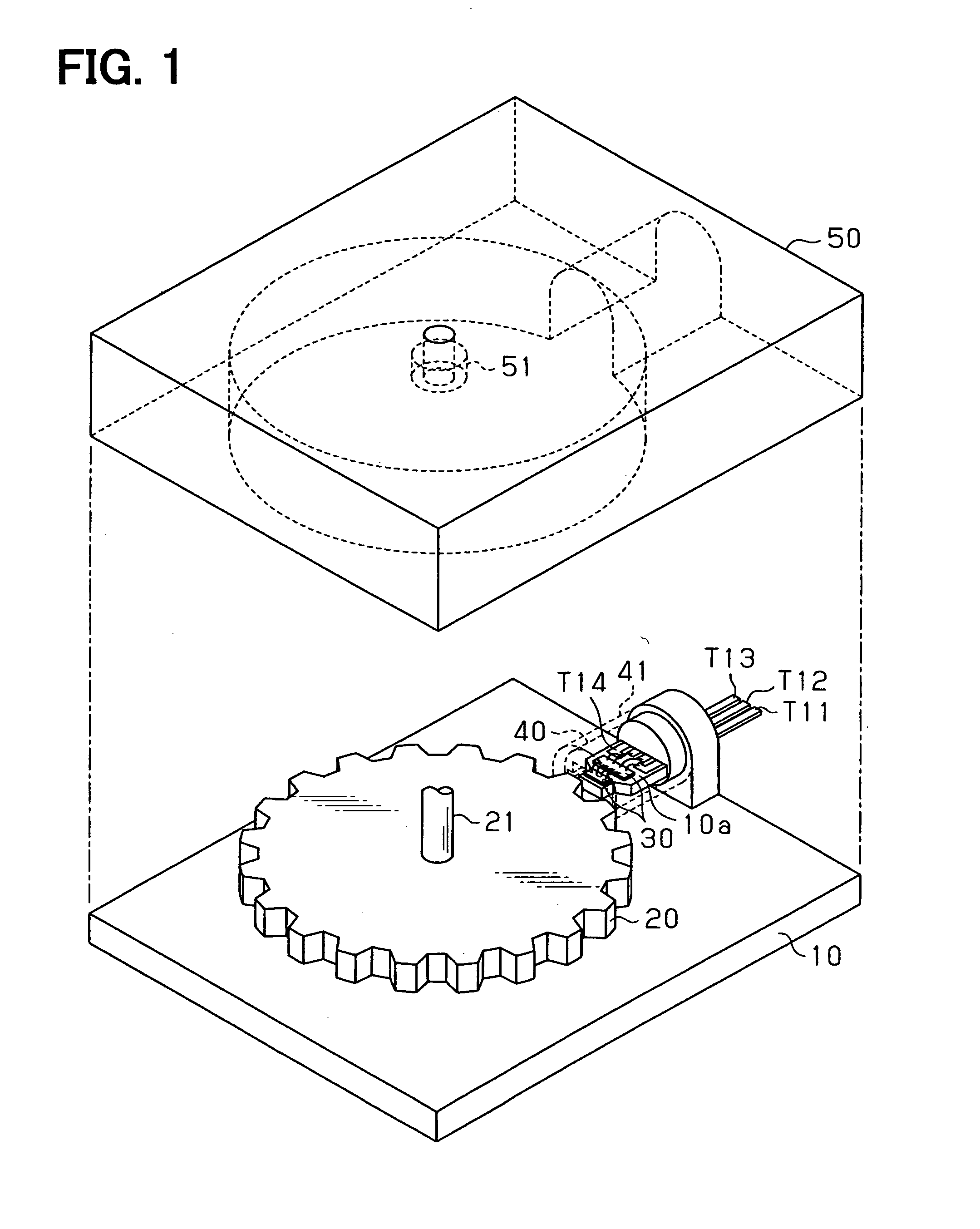
[0033] As shown in FIG. 1, the rotation detecting device is comprised of a housing 10, a gear-teeth type magnetic rotor member 20, a magnet-sensing semiconductor chip 30, a biasing permanent magnet 40 and a cover 50.

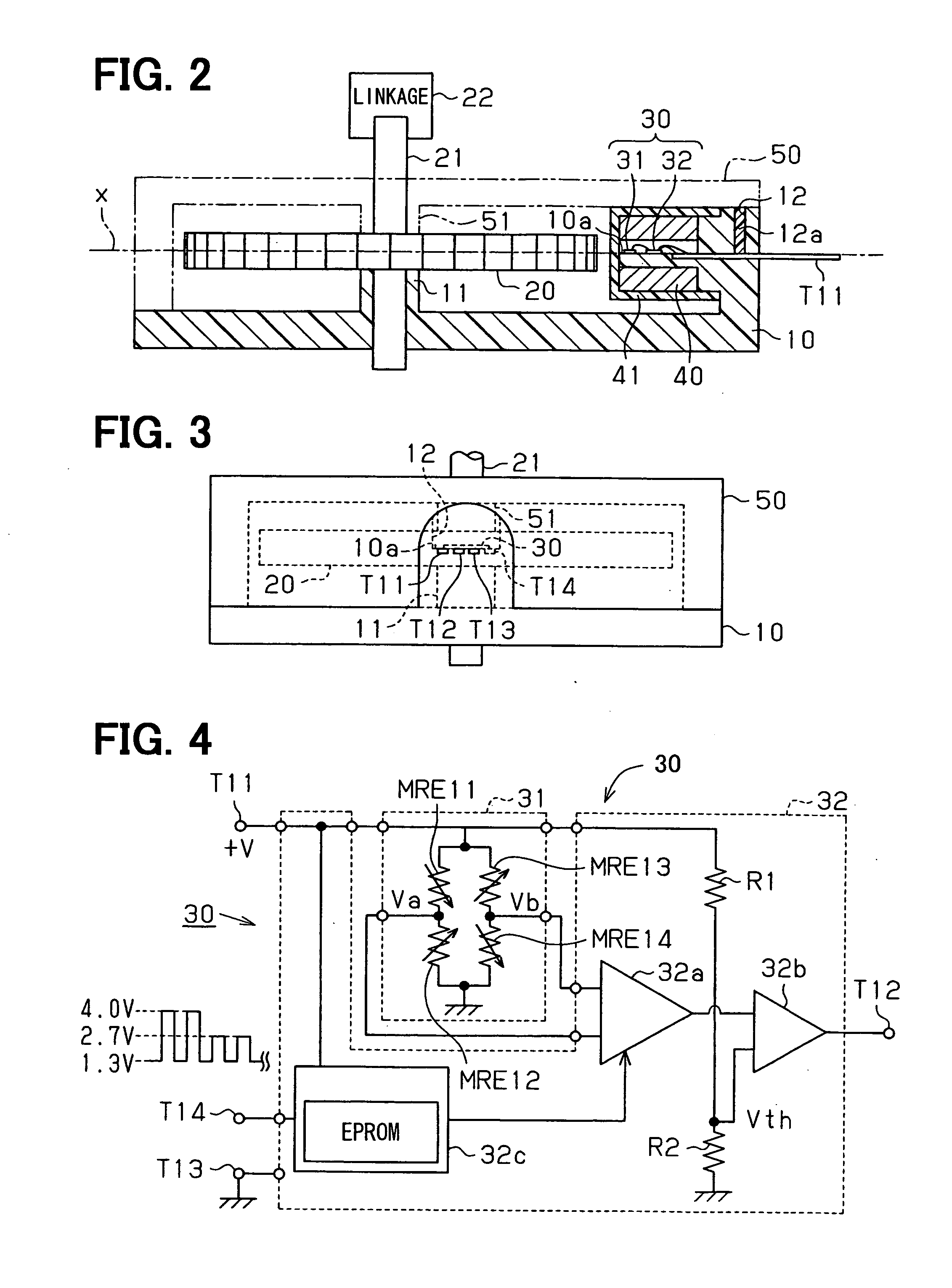
[0034] As shown in FIGS. 2 and 3, the housing 10 is made of an insulative resinous member that has a bearing portion 11 for supporting one end of a rotary shaft 21 of the rotor 20 and a chip mounting surface 10a that is formed perpendicular to the rotary shaft 21 on an imaginary plane x extending through the axially middle portion of the rotor member 20. The semiconductor chip 30, which includes a magnetic sensor chip 31 and a signal processing chip 32, is directly fixed to the chip mounting surface 10a. Because the bearing portion 11 and the chip mounting surface 10a are integrally formed with the housing 10, it is easy to...


PUM


Abstract

A rotation detecting device for detecting a rotating object includes a housing having a bearing and an mounting surface, a rotor member having magnetic peripheral portion and a rotary shaft that is supported by the bearing, a biasing permanent magnet for providing magnetic field around the mounting surface and the magnetic peripheral portion, an IC sensor chip including plural magnetic sensor elements disposed on the mounting surface to provide a sensing signal related to change in magnetic field around the sensor elements, and an IC signal processing chip that provides a rotation signal according to the sensing signal. In this device, the bearing and the mounting surface are integrally formed into the housing at a prescribed distance to secure an unchanged air gap distance.

Description

CROSS REFERENCE TO RELATED APPLICATION [0001] The present application is based on and claims priority from Japanese Patent Applications 2004-319566, filed Nov. 2, 2004 and 2005-56327, filed Mar. 1, 2005, the contents of which are incorporated herein by reference. BACKGROUND OF THE INVENTION [0002] 1. Field of the Invention [0003] The present invention relates to a rotation detecting device for detecting rotation of a vehicle engine, wheel rotation speed or the like and, particularly, a rotation detecting device that employs magnetoresistance elements or hall elements. [0004] 2. Description of the Related Art [0005] U.S. Pat. No. 6,366,079 B1 or JP-A-2001-153683, which is a publication of its counterpart Japanese patent application, discloses a common rotation detecting device. Such a rotation detecting device provides rotation data of an engine crankshaft by detecting changes in a magnetic field caused by rotation of a rotary magnetic member that is rotated by the engine crankshaft....

Claims


Application Information

Patent Timeline
Patent Type & Authority Applications(United States)
IPC IPC(8): G01B7/30
CPCG01D3/022G01D5/147G01D5/24452G01D5/2448G01P3/487G01D18/001
Inventor TOKUHARA, MINORUKATO, YUKIHIRO
Owner DENSO CORP
Why Eureka
Try Eureka