Radio frquency identification tag apparatus for tire in radio freqeuncy identification system

a radio frequency identification and tire technology, applied in the direction of instruments, burglar alarm mechanical actuation, sensing by electromagnetic radiation, etc., can solve the problems of reducing the adhesion between the tire and the rfid tag, secular change, deterioration of the rf characteristics, etc., to improve the impedance characteristic of an antenna and increase the adhesion

Active Publication Date: 2006-05-11
HYUNDAI AUTONET
View PDF5 Cites 17 Cited by
  • Summary
  • Abstract
  • Description
  • Claims
  • Application Information

AI Technical Summary

Benefits of technology

[0015] Therefore, an object of the present invention is to provide a radio frequency identification tag apparatus which is able to increase the adherability between a radio frequency identification tag for a tire and the tire and improve the impedance characteristic of an antenna by forming holes on the radio frequency identification tag in various shapes.

Problems solved by technology

As described above, since the tire and the RFID are constructed of a different heterogeneous medium, this leads to a problem that the adherability between the tire and the RFID tag becomes lowered.
Further, because the adherability between the tire and the RFID tag is lowered, this may bring about a secular change in the apparatus aspect, such as a change of a metallic antenna or substrate.
Resultantly, this may lead to the deterioration of RF characteristics which can be referred to as the index of RFID performance.
Further, due to an apparatus problem that the tire is lack of an element playing the role of supporting except for rubber layers surrounding the tire, there is a high possibility that the stimulus of a heterogeneous medium will be applied to the rubber layers as the RFID tag is shifted within the tire, which may bring about a defect such as a tire burst.

Method used


Image

  • Radio frquency identification tag apparatus for tire in radio freqeuncy identification system
  • Radio frquency identification tag apparatus for tire in radio freqeuncy identification system
  • Radio frquency identification tag apparatus for tire in radio freqeuncy identification system

Examples


Embodiment Construction

[0029] Preferred embodiments of the present invention will now be described in detail with reference to the accompanying drawings. In the following description, only parts needed to understand operation according to the present invention will be described and other details are omitted so as not to obscure the subject matter of the present invention.

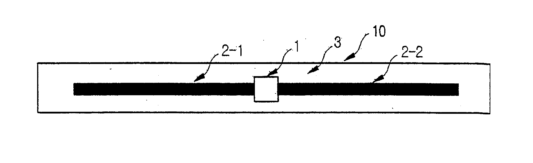
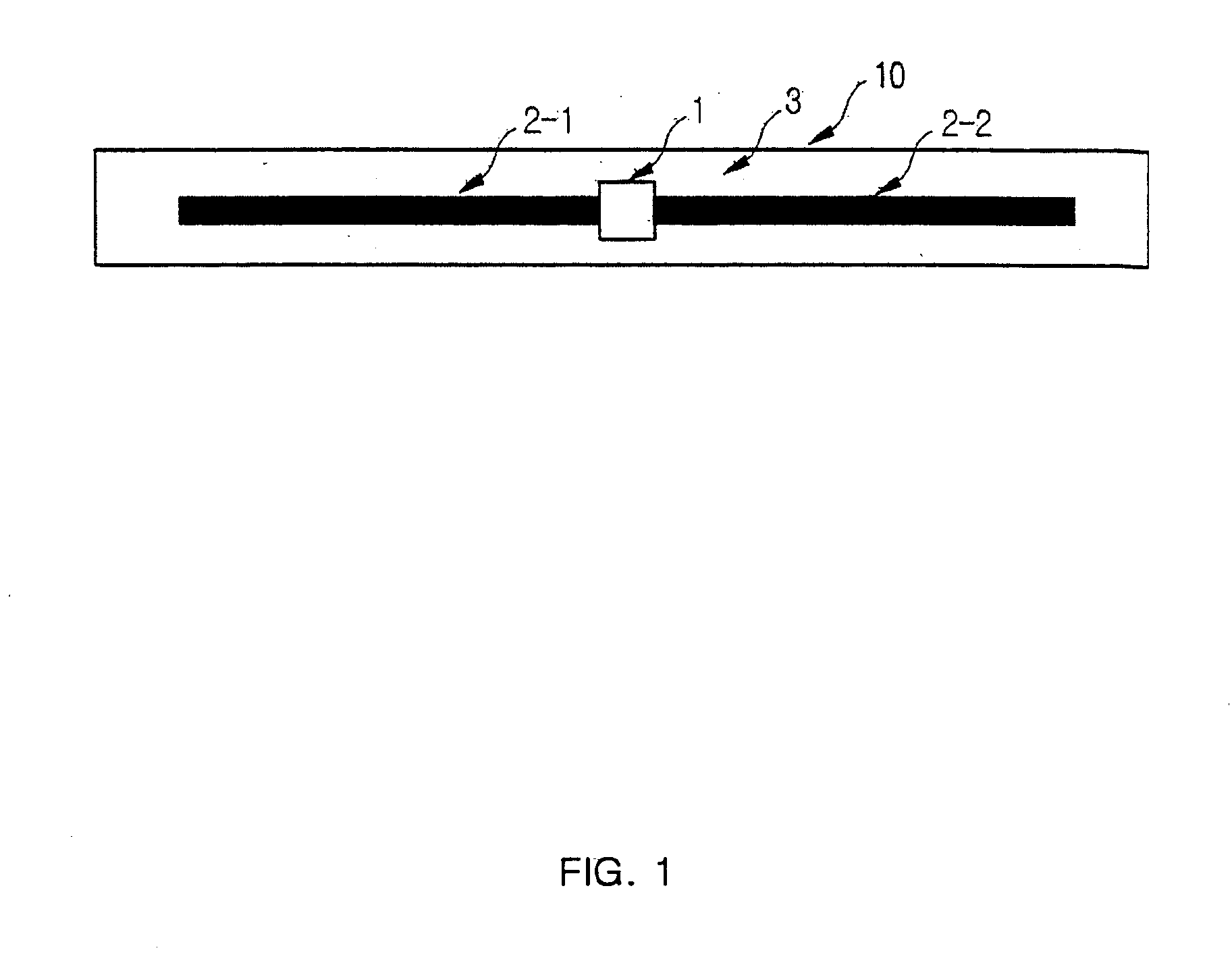
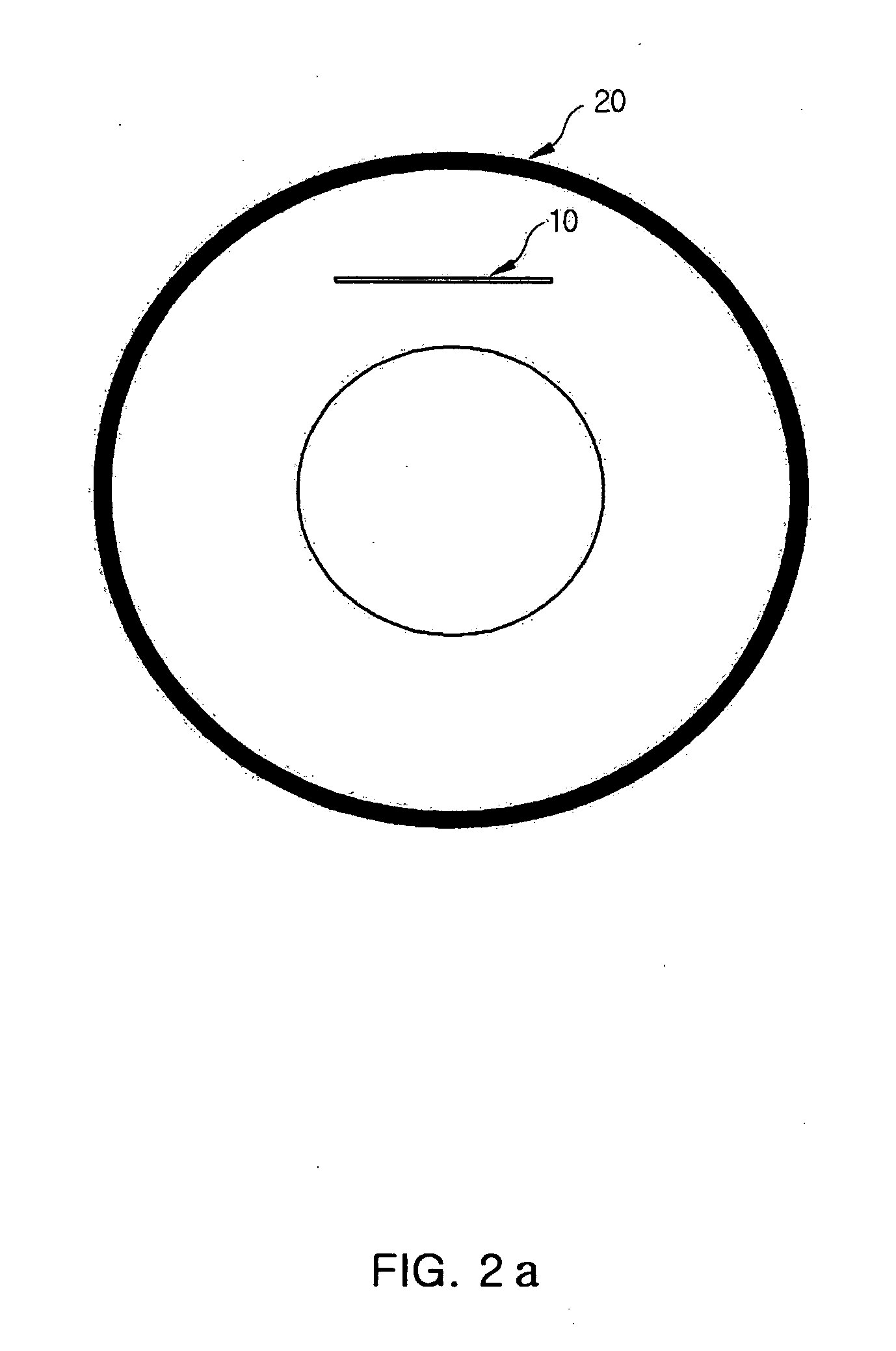
[0030]FIG. 3 is a view showing a radio frequency identification tag apparatus for a tire according to a first embodiment of the present invention. FIG. 4 is a view showing a radio frequency identification tag apparatus for a tire according to a second embodiment of the present invention. FIG. 5a is a plane perspective view of a tire in case the radio frequency identification tag for a tire of the first embodiment is inserted into the tire. FIG. 5b is a side perspective view of a tire in case the radio frequency identification tag for a tire of the first embodiment is inserted into the tire. FIG. 6a to 6d are views showing various shapes ...


PUM


Abstract

The present invention discloses a radio frequency identification tag apparatus for a tire in a radio frequency identification system (hereinafter, referred to as a ‘RFID system’). The radio frequency identification tag apparatus for a tire in a radio frequency identification system, which has a reader for transmitting a strong radio frequency signal to peripheral areas, comprises: a substrate with a plurality of holes having a predetermined shape; a radio chip housed in the substrate, storing the characteristic information of the tire, and operated upon receipt of the radio frequency signal to modulate the characteristic information and output them in the radio frequency signal received from the reader; and an antenna housed in the substrate, having a symmetrically uniform flexion shape relative to the radio chip, receiving the radio frequency signal to provide the same to the radio chip, and receiving the radio signal containing the characteristic information from the radio chip to transmit the same in midair.

Description

BACKGROUND OF THE INVENTION [0001] 1. Field of the Invention [0002] The present invention relates to a radio frequency identification tag apparatus for a tire in a radio frequency identification system (hereinafter, referred to as a ‘RFID system’), and more particularly to, a radio frequency identification tag apparatus for a tire. [0003] 2. Description of the Background Art [0004] Recently, the ubiquitous RFID technology is rising. The term ‘ubiquitous’ means a radio communication environment where a user can access freely to a network regardless of location without being conscious of a computer or network. The RFID is a key factor which becomes a clue to the ubiquitous computing revolution, which enables to send and receive data on the history of items necessary for daily life, commodities, etc. by embedding radio chips, instead of conventional barcodes, for storing the history of the items or commodities in the items or commodities. Thus the RFID is applicable to the history, dis...

Claims


Application Information

Patent Timeline
Patent Type & Authority Applications(United States)
IPC IPC(8): G08B13/14
CPCB60C23/0452B60C23/0493G06K19/07749G06K19/07764H01Q1/2241H01Q1/36H01Q1/38H01Q9/16G06K7/10
Inventor CHOI, SANG HOONCHUN, DONG PILKWON, DAE HYUKNA, HEU KYONGKIM, SANG KOOKCHO, HANG KEELEE, WON JO
Owner HYUNDAI AUTONET
Why Eureka
Try Eureka