Portable retractable adjustable cargo rack assembly

a cargo rack and adjustable technology, applied in the direction of vehicle components, supplementary fittings, other load-carrying vehicles, etc., can solve the problems of not being very successful in the marketplace today, and the difficulty of accessing the cargo area

Inactive Publication Date: 2006-05-11
ERVIN ERIC EDWIN
View PDF0 Cites 5 Cited by
  • Summary
  • Abstract
  • Description
  • Claims
  • Application Information

AI Technical Summary

Benefits of technology

[0007] This invention is a roof mounted cargo rack assembly intended to affix to a pre-existing base structure (or cargo rack—but not limited to such) to aid in loading / unloading cargo on vehicles that may be too tall for the user. This invention consists of two roller housings containing roller mechanisms (such as roller bearings or the like) within the housing, a bottom plate that attaches to the roller housing, and a longitudinal member joining the two roller housings. Each roller housing attaches to a pre-existing perpendicular cross-member (with respect to the lengthwise direction of the vehicle) and allows the assembly to move over the surface of the cross-members from a position atop the vehicle to a loading / unloading position near juxtaposed to the vehicle rooftop—while remaining attached to the pre-existing framework. The roller housing longitudinal joining member (positioned lengthwise with respect to the lengthwise direction of the vehicle) can be adjusted to accommodate different sized preexisting vehicle cargo racks. The longitudinal member joining the roller housing may also be removed to accommodate easy breakdown and storage.

Problems solved by technology

Therefore there may exist a problem of accessing the cargo area because of the height of vehicles such as SUVs, Vans, etc.
Unfortunately they have not been very successful in today's marketplace.

Method used


Image

  • Portable retractable adjustable cargo rack assembly
  • Portable retractable adjustable cargo rack assembly
  • Portable retractable adjustable cargo rack assembly

Examples


Embodiment Construction

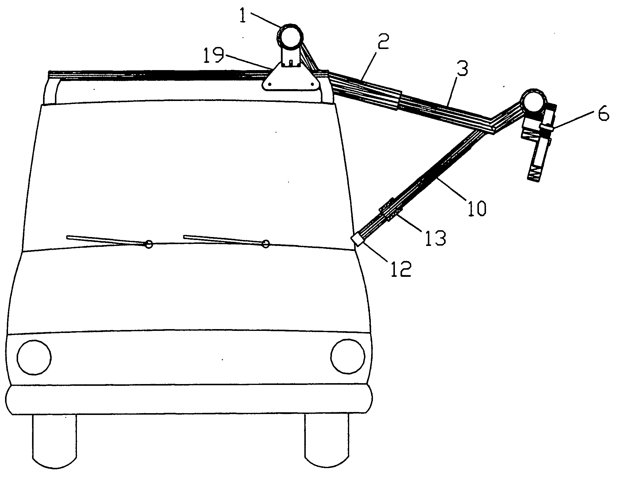
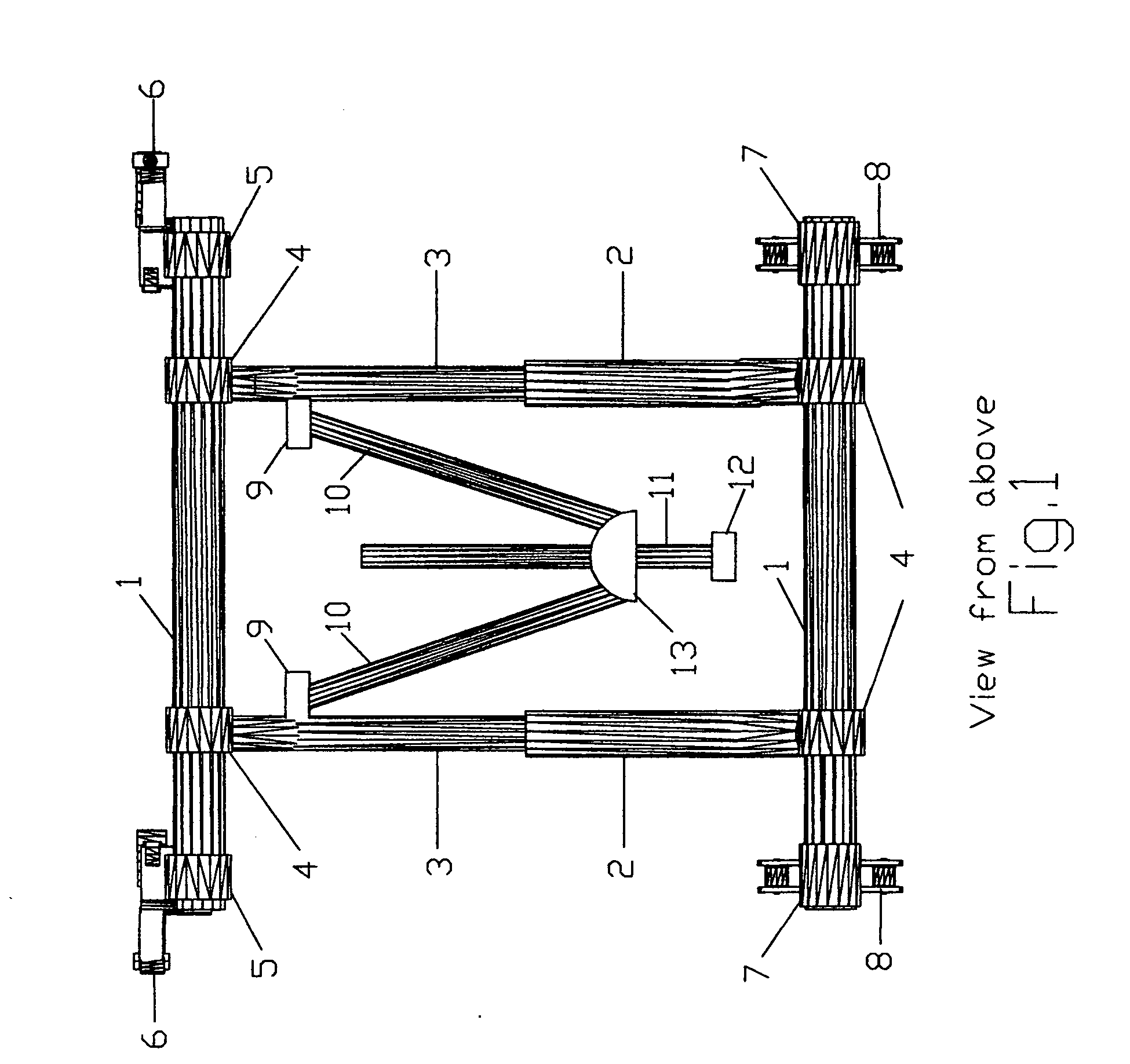
[0021] Beginning with FIG. 1, this view depicts the framework of this invention as two longitudinal rails (1) (tubular or the like) spaced parallel—joined by two parallel rails each (2 and 3) (tubular or the like) in a perpendicularly longitudinal position with respect to 1. The rails 2 and 3 are constructed such that 3“telescopes” into 2. This allows the invention the ability to be adjusted to fit the width of load and / or roof of the vehicle. The rails 2 and 3 are joined to rails 1 such that 2 and 3 will have the ability to move slideably over the surface of 1—allowing adjustments for length of cargo and / or pre-existing vehicle rack. Joined to rail(s) 3 are two hinged connectors 9 which allow the support rails (10) and support extension (11) to move in a circular motion about an axis passing through each hinge (9). The support rail(s) 10 are connected at opposite ends from 9 by two plates positioned on the top and bottom surfaces of 10 allowing hinged movement of 10 as 2 and 3 are ...


PUM


Abstract

A portable retractable adjustable cargo rack assembly intended to affix to an existing cargo support system of a vehicle, meaning roof-mounted (but not limited to such), and to deploy to a near juxtaposed position to facilitate loading and unloading of cargo, thereby alleviating the need for vertical assistance or mechanical devices to deploy or secure. The assembly includes roller bearing housings that attach securely to the existing vehicle rack cross-members, and are secured to the portable rack assembly allowing movement over the surface of the pre-existing cross-members from a secured position atop the vehicle to an extended loading/unloading position at a near-juxtaposed position with respect to the plane of the roof of the vehicle—while remaining attached to pre-existing base frame. This invention also includes a clamping device that secures the assembly to the existing vehicle rack atop the vehicle. Two or more telescoping cross-shafts are included in this invention that may be used to secure and/or support cargo while atop base structure. A retractable support brace attached to the cross-shafts can be deployed to rest against the vehicle or telescoped to the ground to give support while loading/unloading. Two shafts or frames, positioned opposite each other, lengthwise with respect to the direction of the vehicle, connecting the roller housing and clamps to the assembly, respectfully.

Description

BACKGROUND OF THE INVENTION [0001] 1. Field of the Invention [0002] This invention pertains to a portable retractable adjustable cargo rack assembly that mounts to, and is supported by, a pre-existing base structure such as a pre-existing cargo rack atop a vehicle (but not limited to such), to facilitate loading and unloading of cargo. [0003] 2. Discussion of Prior Art [0004] At present there are a great number of vehicles on the market that are designed to facilitate cargo atop the vehicle. Most systems are comprised of two “rails” that are permanently (not particularly) secured to the roof of the vehicle and are positioned parallel and length-wise with respect to the longitudinal axis of the vehicle. A pair of perpendicular rails (with respect to the longitudinal axis of the vehicle) that attach to the lengthwise rails are positioned such that adjustments can be made to facilitate cargo between, or atop, said perpendicular rails. This system can provide means of facilitating cargo...

Claims


Application Information

Patent Timeline
Patent Type & Authority Applications(United States)
IPC IPC(8): B60P9/00
CPCB60R9/042
Inventor ERVIN, ERIC EDWIN
Owner ERVIN ERIC EDWIN
Why Eureka
Try Eureka