Pneumatically powered rotary tool having linear forward and reverse switch

a technology of pneumatic power and rotary tools, which is applied in the direction of manufacturing tools, drilling pipes, portable drilling machines, etc., can solve the problems of awkward operation or distance from the trigger of the tool

Inactive Publication Date: 2006-05-18
BLACK & DECKER INC
View PDF24 Cites 48 Cited by
  • Summary
  • Abstract
  • Description
  • Claims
  • Application Information

AI Technical Summary

Benefits of technology

[0004] Accordingly, the present invention is directed to pneumatically powered (i.e., air powered) rotary tool such as an impact wrench, an air drill, an air ratchet, or the like, having a linearly actuated forward and reverse switch positioned proximal to the tool's trigger for ease of operation by allowing the user to actuate the switch with the thumb and / or index finger of the hand holding the tool, without removing the hand from the handle assembly.

Problems solved by technology

Current pneumatic rotary tools include switch assemblies positioned on the tool housing so that they are distant from the trigger of the tool or wich are awkward to operate.

Method used


Image

  • Pneumatically powered rotary tool having linear forward and reverse switch
  • Pneumatically powered rotary tool having linear forward and reverse switch
  • Pneumatically powered rotary tool having linear forward and reverse switch

Examples


Embodiment Construction

[0015] Reference will now be made in detail to the presently preferred embodiments of the invention, examples of which are illustrated in the accompanying drawings.

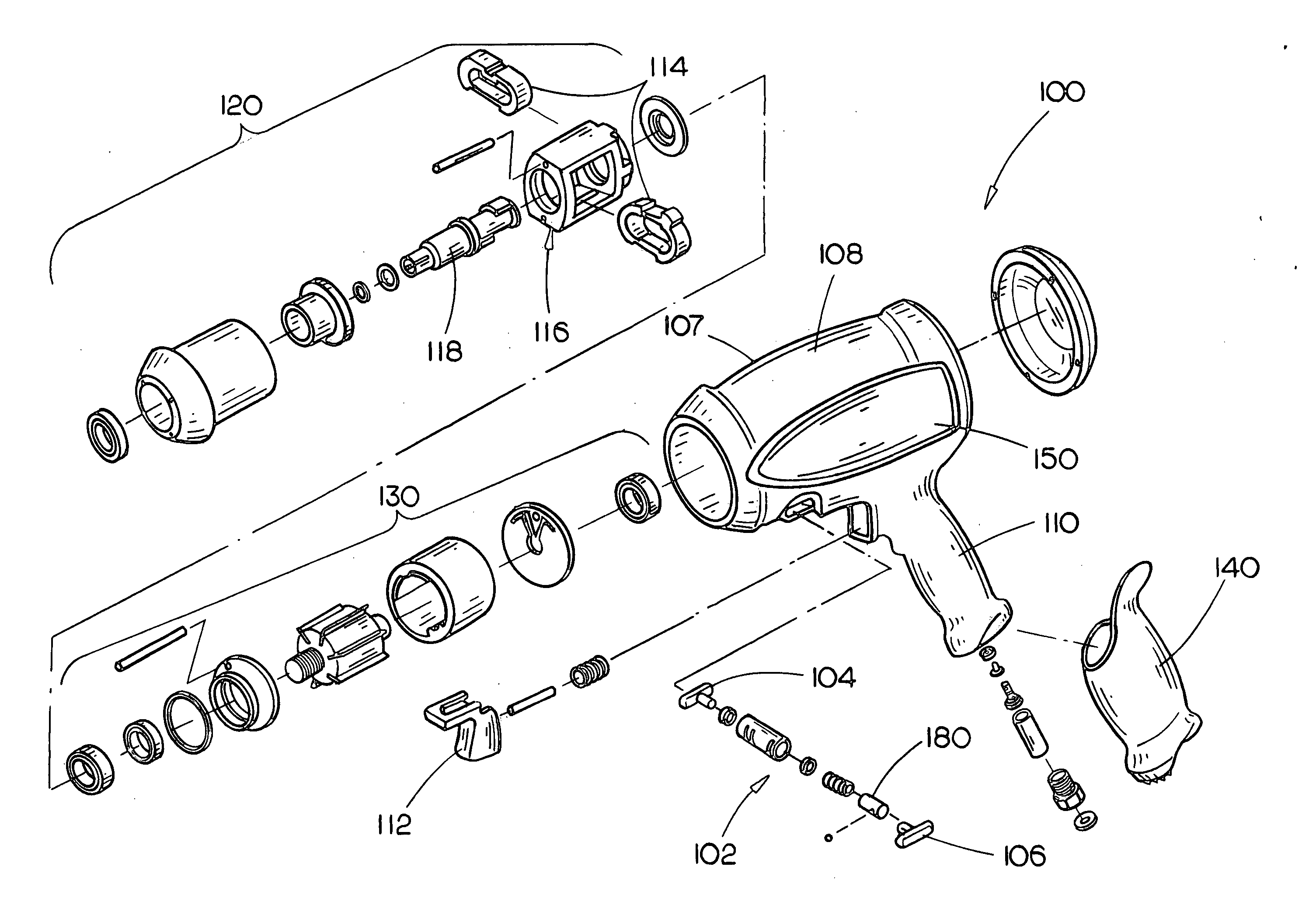
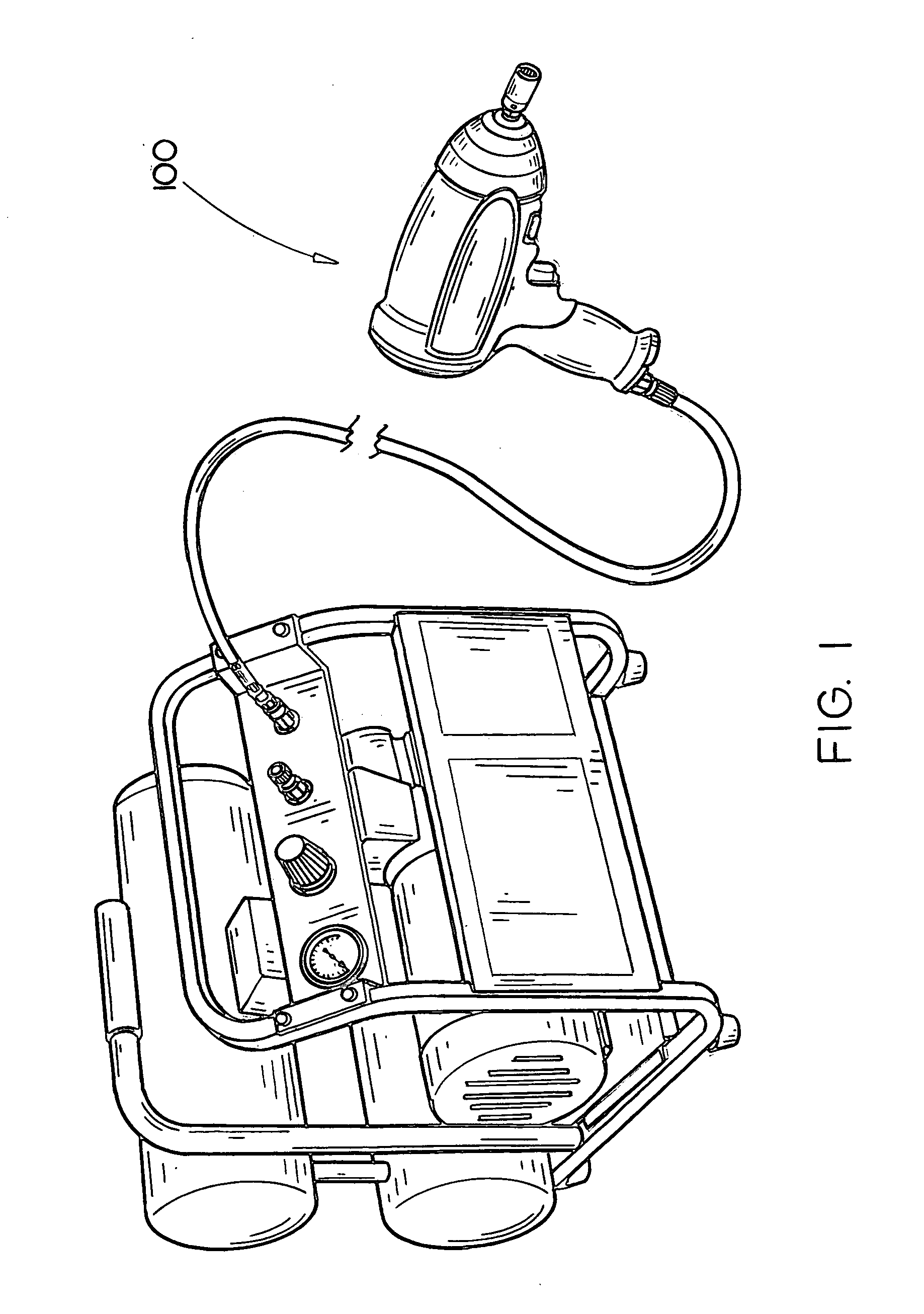
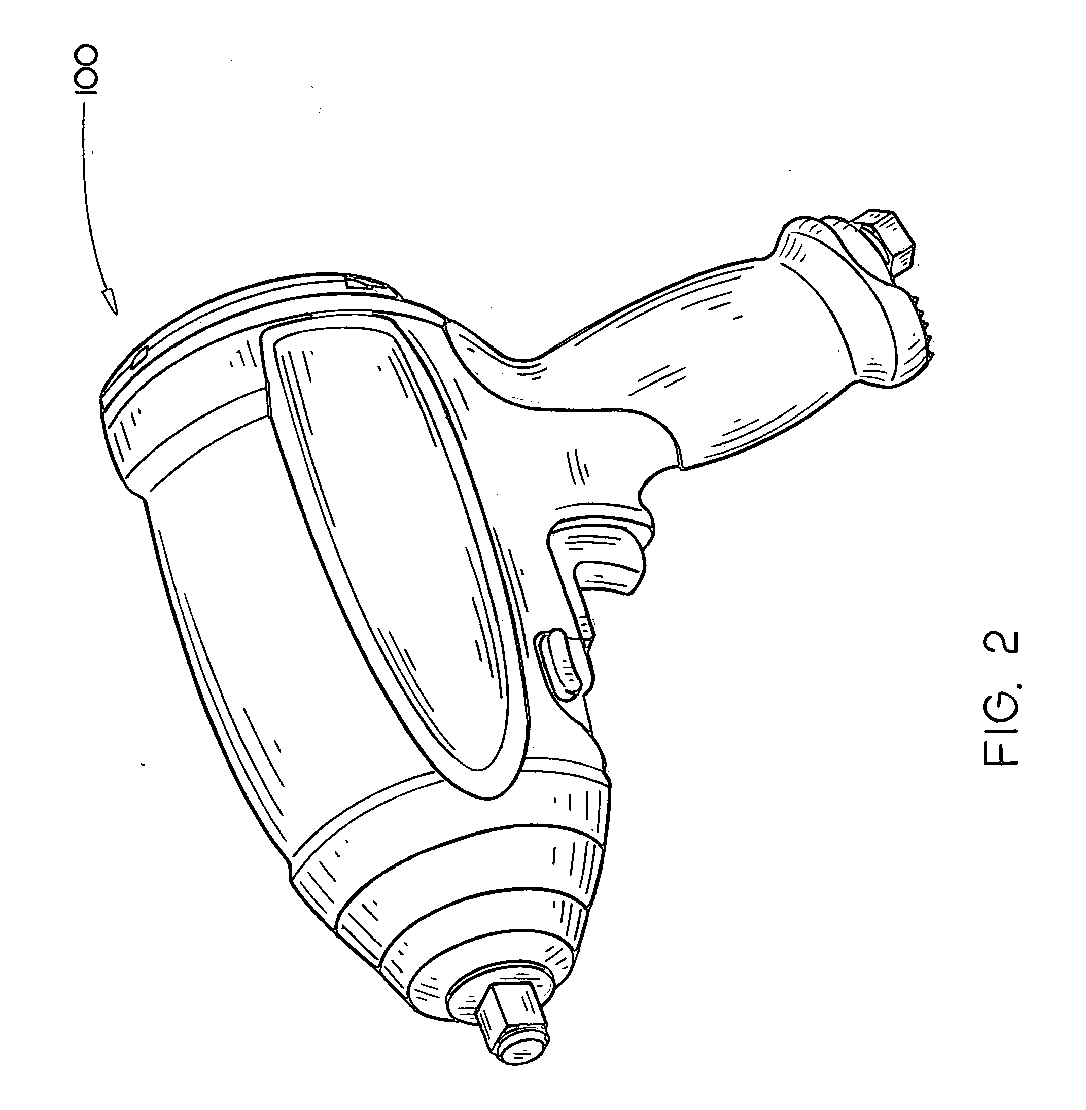
[0016]FIGS. 1 through 4 illustrates a pneumatically powered rotary tool, specifically a pneumatic impact wrench 100, having a linear forward and reverse switch assembly 102 in accordance with an exemplary embodiment of the present invention. As shown, the impact wrench 100 includes a housing 107 having a body portion 108 and a handle portion 110. The handle portion 110 extends from the body portion 108 for being gripped by the hand of a user operating the pneumatically powered impact wrench 100. The housing 107 may be at least partially coated with an elastomeric material 140&150 (e.g., plastic, rubber, synthetic rubber, or the like) for protecting the housing 107. In exemplary embodiments, this elastomeric material 140 may at least partially extend over the handle portion 110 for providing ease of grip of the handle por...


PUM

PropertyMeasurementUnit
pressureaaaaaaaaaa
torqueaaaaaaaaaa

Abstract

A pneumatically powered rotary tool includes a linear forward and reverse switch assembly for alternatively setting the air motor of the tool to rotate the drive assembly of the tool in either of the clockwise direction or the counterclockwise direction. The switch assembly slides linearly along an axis generally perpendicular to the drive assembly between a first position for setting the air motor to rotate the drive assembly in the clockwise direction and a second position for setting the air motor to rotate the drive assembly in the counterclockwise direction. The switch assembly is positioned adjacent to the trigger so that the switch assembly can be slid between the first position and the second position by the index finger and thumb of the hand of the user gripping the handle portion without releasing the handle portion.

Description

CROSS-REFERENCE TO RELATED APPLICATIONS [0001] The present application claims priority under 35 U.S.C. §119(e) to U.S. Provisional Application No. 60 / 541,883 entitled: User Friendly Air Power Tools filed Feb. 4, 2004 and U.S. Provisional Application No. 60 / 543,325 entitled: User Friendly Air Power Tools filed Feb. 10, 2004. The U.S. Provisional Applications, Ser. Nos. 60 / 541,883 and 60 / 543,325, are herein incorporated by reference in their entireties.FIELD OF THE INVENTION [0002] The present invention generally relates to the field of pneumatically powered tools and, in particular, to a pneumatically powered rotary tools having a linearly actuated forward and reverse switch positioned adjacent to the tool's trigger for ease of operation. BACKGROUND OF THE INVENTION [0003] Many pneumatically powered rotary tools, such as impact wrenches, air drills, air ratchets and the like, include a switch assembly which allows a user to both tighten and loosen fasteners, such as lug nuts or bolts...

Claims


Application Information

Patent Timeline
Patent Type & Authority Applications(United States)
IPC IPC(8): B23B45/04
CPCB25B21/00B25B21/02
Inventor ETTER, MARK A.MORGAN, FREDRICK M.
Owner BLACK & DECKER INC
Why Eureka
Try Eureka