

Processes for separating metals from metal salts
a technology of metal salt and separation process, which is applied in the field of electrochemical reduction of metal compounds, can solve the problems of large quantities of sodium salt, high market price of sodium, and increase the cost of raw materials for making sodium borohydrid
- Summary
- Abstract
- Description
- Claims
- Application Information
AI Technical Summary
Problems solved by technology
Method used
Image

Examples
example 1
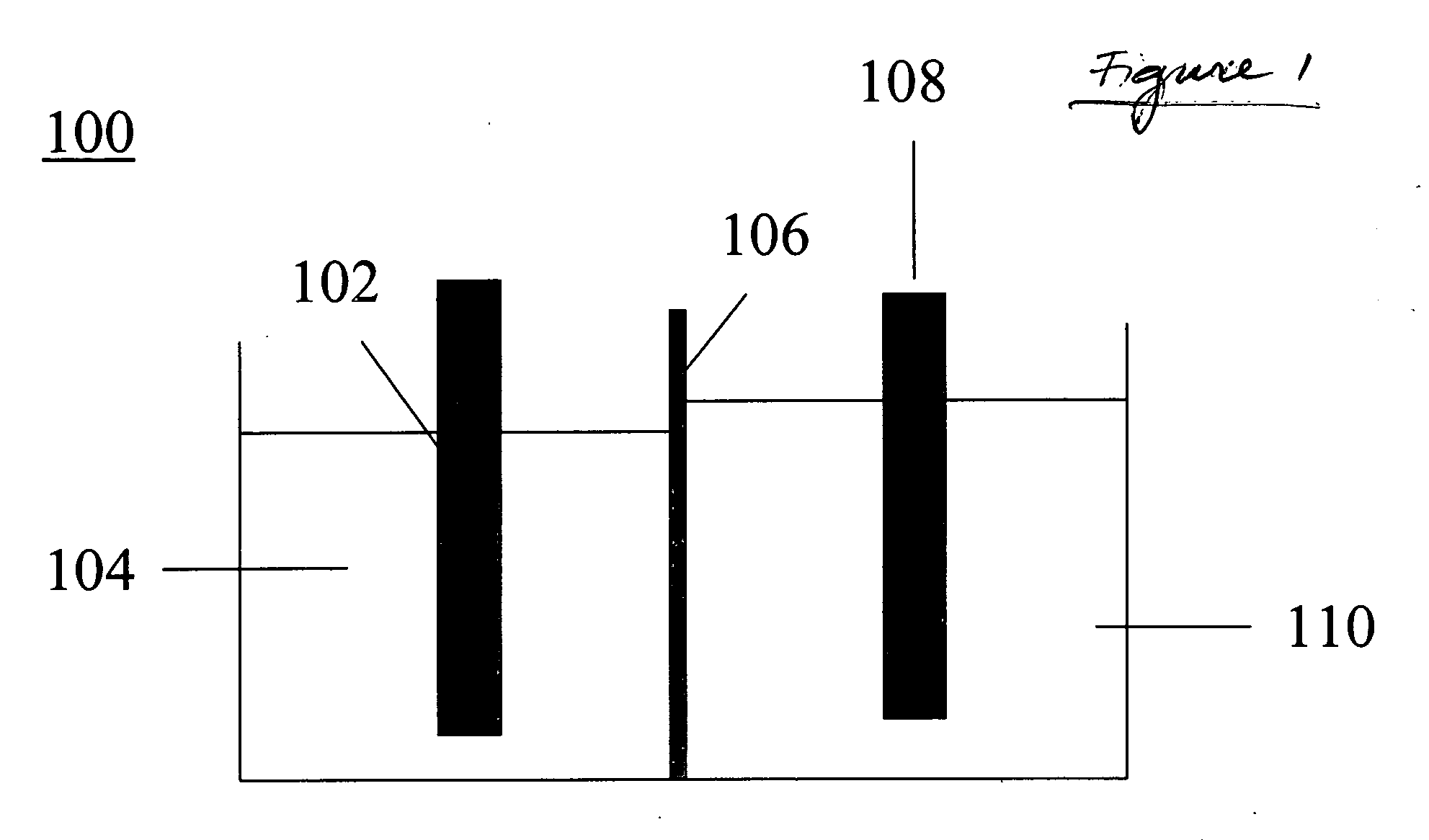
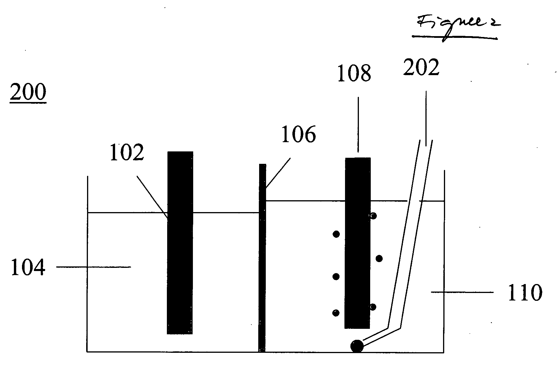
[0068] A reaction flask was charged with about 200 g of 5.5 weight percent NaBO2 aqueous solution. A tube with a NaSICON bottom was inserted into the solution. The tube contained 1.03 gram of sodium metal. Embedded into the sodium metal was a nickel wire. Collectively, the sodium metal and the nickel wire comprised the cathode. The tube bottom comprised the membrane or separator. The volume inside the tube defined the cathode compartment and the volume outside the tube, but inside the reaction flask, comprised the anode compartment. The aqueous metaborate solution comprised the anolyte. The anode itself was a nickel wire wrapped around a nickel plate, the combination of the wire and plate together comprising the anode.
[0069] The reaction flask was heated to about 115° C. and pressurized to about 10 psi. Under these conditions, the sodium in the cathode compartment was molten. A potential of about 5 V was applied across the anode and the cathode. After 606 mAh of current passed thro...
example 2
[0070] A reaction flask was charged with about 150 g of NaBO2.4 H2O (sodium metaborate tetrahydrate). A Na-β″-alumina tube was inserted into the solution. The tube contained 0.99 gram of sodium metal. Embedded into the sodium metal was a nickel wire. Collectively, the sodium metal and the nickel wire comprised the cathode. The tube bottom comprised the membrane or separator. The volume inside the tube was the cathode compartment and the volume outside the tube, but inside the reaction flask, comprised the anode compartment. The sodium metaborate comprised the anolyte. The anode itself was a nickel wire wrapped around a nickel plate, the wire and plate together comprising the anode.
[0071] The reaction flask was heated to about 135° C. and pressurized to about 10 psi. Under these conditions, the sodium in the cathode compartment was molten, and the sodium metaborate tetrahydrate in the anode compartment was molten. A potential of about 5 V was applied across the anode and the cathode...
example 3
[0072] A reaction flask was charged with about 200 g of 9.1 weight-% Na2CO3 aqueous solution. A tube with a NaSICON bottom was inserted into the solution. The tube contained about 1 gram of sodium metal. Embedded into the sodium metal was a nickel wire. Collectively, the sodium metal and the nickel wire comprised the cathode. The tube bottom comprised the membrane or separator. The volume inside the tube was the cathode compartment and the volume outside the tube, but inside the reaction flask comprised the anode compartment. The aqueous carbonate solution comprised the anolyte. The anode itself was a nickel wire wrapped around a nickel plate, the wire and plate together comprising the anode.
[0073] The reaction flask was heated to about 115° C. and pressurized to about 10 psi. Under these conditions, the sodium in the cathode compartment was molten. A potential of about 5 V was applied across the anode and the cathode. After passing 500 mAh of current through the cell, it was coole...
PUM
| Property | Measurement | Unit |
|---|---|---|
| Temperature | aaaaa | aaaaa |
| Temperature | aaaaa | aaaaa |
| Temperature | aaaaa | aaaaa |
Abstract
Description
Claims
Application Information