
Pressurized sonobuoy deployment system

Active Publication Date: 2006-05-18
THE BOEING CO
View PDF8 Cites 14 Cited by
  • Summary
  • Abstract
  • Description
  • Claims
  • Application Information

AI Technical Summary

Benefits of technology

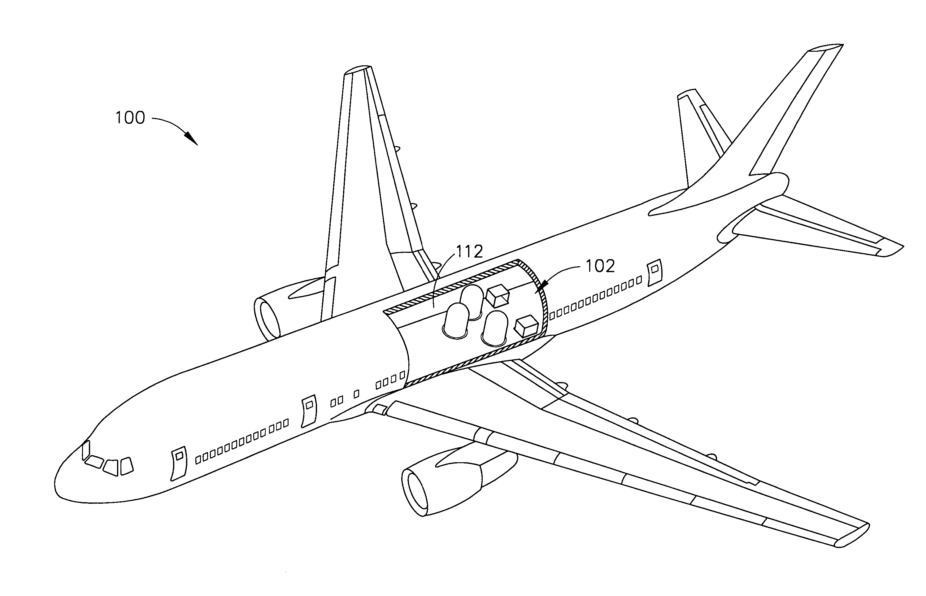
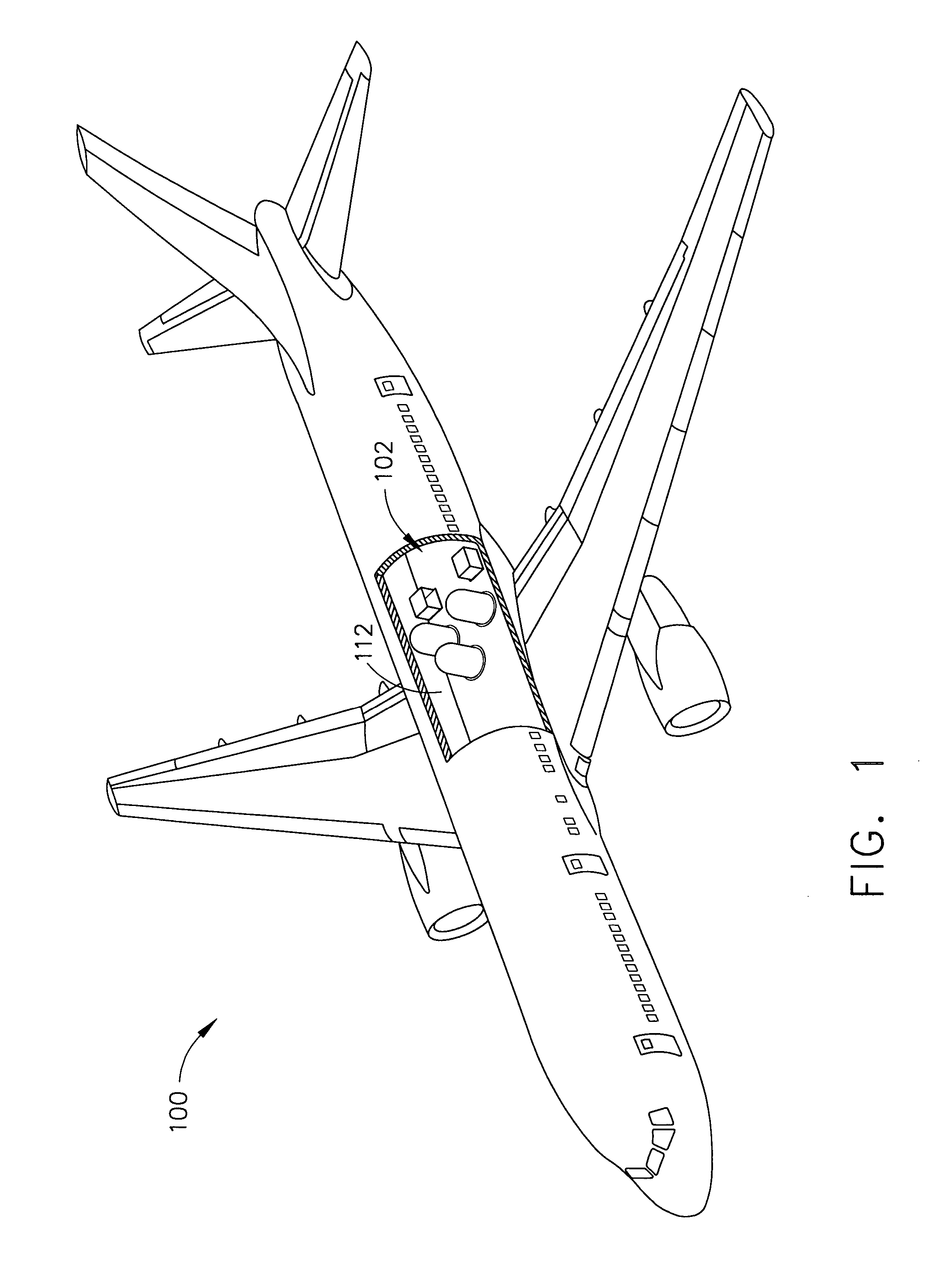
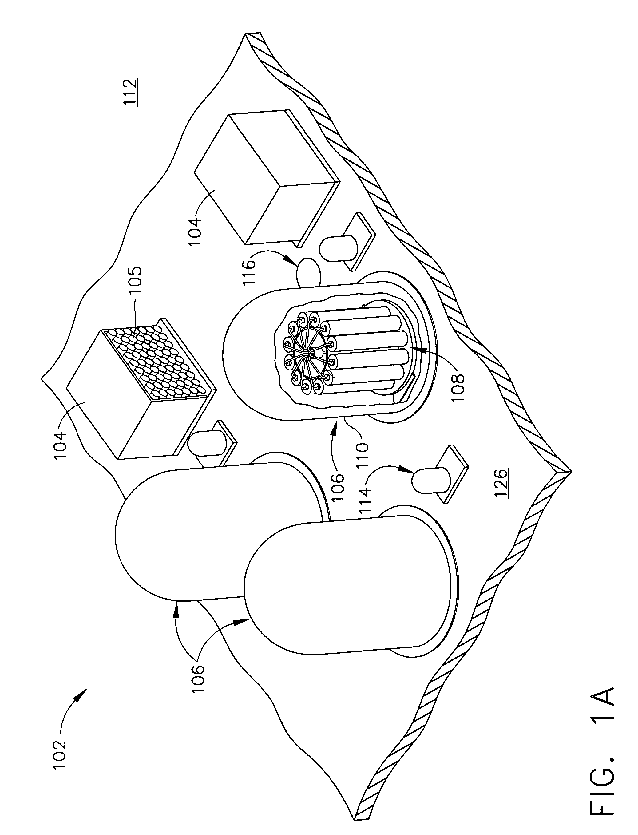
[0008] In another embodiment of the present invention, a sonobuoy launch system includes a pressure dome having a door. When the door is closed the pressure dome maintains a pressure difference between a cabin pressure outside the pressure dome and an ambient pressure inside the pressure dome. A gate valve in a floor under the pressure dome allows the pressure difference to be reduced when the gate valve is closed and allows the cabin pressure to be maintained inside the pressure dome so that the door can be opened. A rotary launcher inside the pressure dome rotates a sonobuoy into a loading position and sonobuoys are loaded while the gate valve is closed and the door is open. A pneumatic system connected to the rotary launcher forces the sonobuoy from its SLC when the gate valve is open and the door is closed.

Problems solved by technology

Release of sonobuoys from higher altitudes may present problems in deploying sonobuoys from pressurized aircraft.
Also, different workload issues may be presented in loading sonobuoys in a launcher depending on the type and configuration of the launcher.

Method used


Image

  • Pressurized sonobuoy deployment system
  • Pressurized sonobuoy deployment system
  • Pressurized sonobuoy deployment system

Examples


Embodiment Construction

[0023] The following detailed description is of the best currently contemplated modes of carrying out the invention. The description is not to be taken in a limiting sense, but is made merely for the purpose of illustrating the general principles of the invention, since the scope of the invention is best defined by the appended claims.

[0024] Broadly, the present invention provides an aircraft and integrated system for launching stores from the aircraft, which may be, for example, a modified jet transport aircraft. The system may also be useful as well for slower, lower flying aircraft and helicopters. The stores may include a variety of devices, for example, chaff buoys, munitions, and marker buoys. A major application, however, is to the launching of sonobuoys, and sonobuoys are referred to throughout as the primary illustrative example without any intended loss of generality. One embodiment of the present invention provides a comprehensive, integrated system for launching large n...


PUM


Abstract

A jet aircraft with integrated, rotary sonobuoy launch system has storage racks for a number of sonobuoys in sonobuoy launch containers; and one or more launcher units in its cabin. Each launcher unit has a pressure shell with a door allowing loading of sonobuoys in sonobuoy launch containers from the storage racks. With the door closed, the inside of the shell can be depressurized for launching a sonobuoy by opening a gate valve that connects the interior of the shell to the exterior of the aircraft. With the gate valve closed, the shell can pressurized so that the door can be opened and sonobuoys reloaded. A control system can be used to rotate a rotary launcher inside each pressure shell so that a selected sonobuoy is moved to a launch position above the gate valve and a launch tube, and a pneumatic system can be used to launch the sonobuoy.

Description

GOVERNMENT RIGHTS [0001] This invention was made with Government support. The Government has certain rights in this invention.BACKGROUND OF THE INVENTION [0002] The present invention generally relates to launching stores from flying vehicles and, more particularly, to launching sonobuoys from aircraft. [0003] A number of different types of dispensers and launchers exist for deployment of sonobuoys from aircraft, such as airplanes and helicopters. Sonobuoys are often deployed into the ocean to aid in the detection of vessels, such as submarines, and may have military as well as other uses. Sonobuoys may be equipped to use echo location, for example, or to detect noise generated by a vessel, and precise determination of location may be facilitated by deploying a number of sonobuoys within a prescribed distance and time period. [0004] A number of different mechanisms have been used for implementing sonobuoy release from the launcher including, for example, cartridge activated devices (...

Claims


Application Information

Patent Timeline
IPC IPC(8): B64C1/22
CPCB64D1/02B64D13/02Y02T50/44Y02T50/40
Inventor PITZER, JON W.OLSEN, MARK
Owner THE BOEING CO
Learn More