Liquid switch, and microchip and mass-analyzing system using the same

Inactive Publication Date: 2006-05-18
NEC CORP
View PDF1 Cites 13 Cited by
  • Summary
  • Abstract
  • Description
  • Claims
  • Application Information

AI Technical Summary

Benefits of technology

[0033] According to these mass spectrometry systems, a sample suitable for the mass spectrometry can be prepared with higher efficiency.
[0034] As have been described above, according to the present invention, the switch structure for precisely con

Problems solved by technology

However, such method is difficult to provide a precise control of a behavior of a very small amount of sample in the chip.
Further, a

Method used


Image

  • Liquid switch, and microchip and mass-analyzing system using the same
  • Liquid switch, and microchip and mass-analyzing system using the same
  • Liquid switch, and microchip and mass-analyzing system using the same

Examples


first embodiment

[0066] In the present embodiment, an example of a liquid switch comprising a member for holding a liquid, which is disposed in a sample damming portion, will be illustrated. This liquid switch can be manufactured by forming a trench on a surface of a quartz substrate. Since the surface of the quartz substrate is hydrophilic, the inner walls of the trench are also hydrophilic surfaces. The apparatus including such switch is free of any external force-applying units such as pump or electric field, and the liquid moves through the channel by the capillary force.

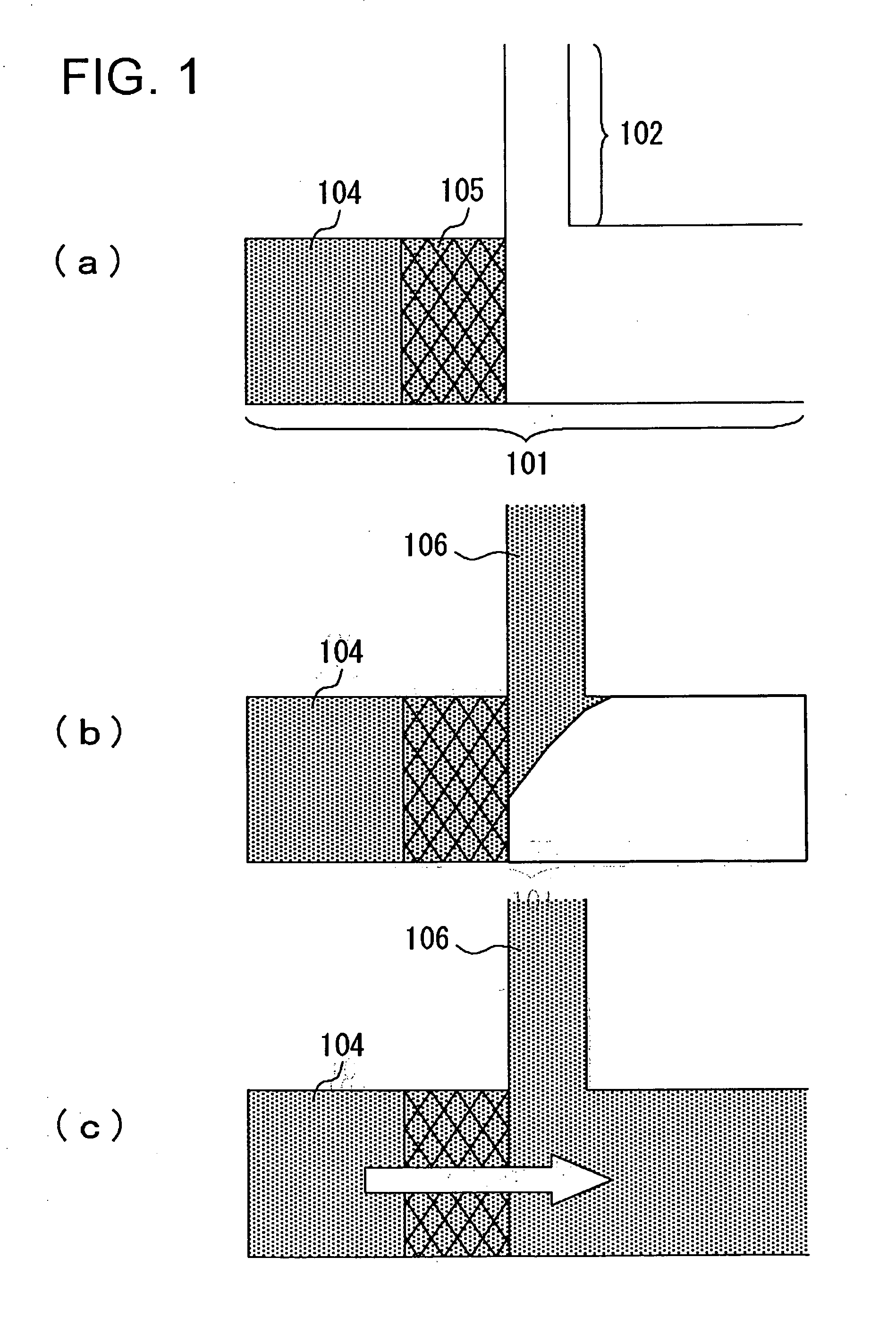
[0067] FIGS. 1(a), 1(b) and 1(c) are plan views of the liquid switch, and more specifically, FIG. 1(a) shows a closing status of the switch, and FIGS. 1(b) and 1(c) show an opening status of the switch. In these figures, a trigger channel 102 is connected to a side surface of a principal channel 101. The trigger channel 102 is capable of adjusting a liquid transferring velocity in the channel by suitably adjusting the degree of...

second embodiment

[0078] The present embodiment relates to a switch construction employing a hydrophobic region as a damming portion material. The liquid switch can be manufactured by forming a trench on a surface of a quartz substrate. Since the quartz substrate is employed, the inner walls of the trench are hydrophilic surfaces. The hydrophobic region is obtained by hydrophobic-processing a lid portion having a quartz glass surface.

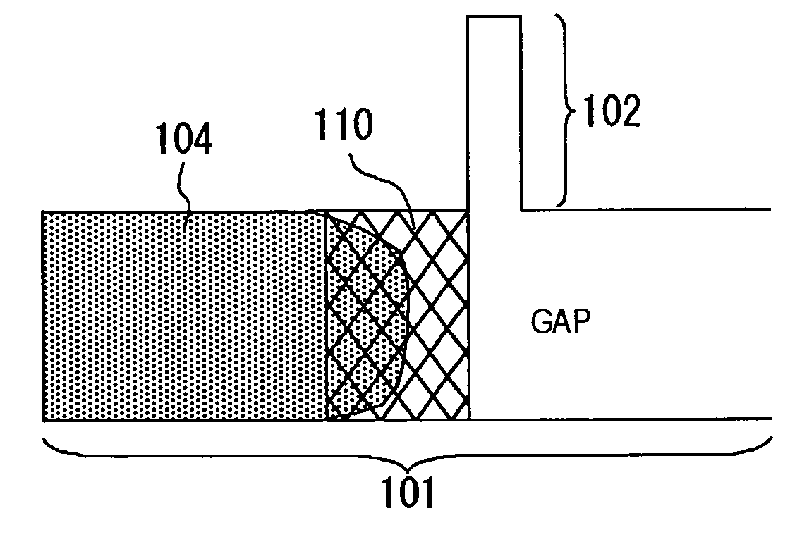
[0079] In this switch, a trigger channel 102 is coupled to a side surface of a principal channel 101 as shown in FIG. 4(a), and an upstream of an intersecting portion thereof in the principal channel 101 is provided with a damming portion 110 composed of a hydrophobic region. The principal channel 101 and the trigger channel 102 except the damming portion 110 composed of the hydrophobic region are hydrophilic regions. The selective preparations of the hydrophilic region and the hydrophobic region are conducted as follows in the present embodiment. More specifically, aft...

third embodiment

[0088]FIG. 6 is a diagram, illustrating an example of a separating apparatus employing a liquid switch in a sample inlet. This separating apparatus utilizes a capillary phenomenon for moving a sample to conduct a separation of the sample according to molecular size by using a channel for separation 540. The apparatus eliminates a need for applying an external force such as electric power, pressure or the like, and also eliminates a need for a driving energy. The separating apparatus has a configuration, in which a channel for separation 540 is provided on a substrate 550. One end of the channel for separation 540 is provided with an air opening 560, and the other end is provided with a buffer injection port 510 for injecting a buffer. The channel for separation 540 is tightly sealed except portions of the buffer injection port 510 and the air opening 560. A sample quantification tube 530 is connected to a beginning of the channel for separation 540, and the other end of the sample q...


PUM

PropertyMeasurementUnit
Sizeaaaaaaaaaa
Surface areaaaaaaaaaaa
Levelaaaaaaaaaa

Abstract

A liquid sample (104) introduced in a main flow passage (101) is held in a dam portion (105), and a trigger liquid (106) is filled in a trigger flow passage (102). In this state, the trigger liquid (106) is further introduced at desired timing into the trigger flow passage (102) so that the front end portion of the level of the trigger liquid (106) is advanced and the front end portion is brought to be into contact with the dam portion (105). This causes the liquid sample (104) to move to the right (downstream side) in the figure, resulting in the liquid sample (104) flowing out to the downstream side of the main flow passage (101). This means that the trigger liquid (106) provides priming to realize a liquid switch.

Description

BACKGROUND OF THE INVENTION [0001] 1. Technical Field [0002] The present invention relates to a liquid switch for controlling a liquid flow, and a microchip and a mass spectrometry system using thereof. [0003] 2. Background Art [0004] In recent years, a micro-total analytical system (μ-TAS), in which chemical operations such as pre-processing, reaction, separating, detection or the like of a sample are conducted on a microchip, is rapidly developing. According to the micro-total analytical system, only a very small amount of a sample is required to be used, and analysis with higher sensitivity can be conducted with smaller environment load. [0005] In patent literature 1, an apparatus for achieving a capillary electrophoresis by a micro channel-type chip having a configuration of being provided with a groove or a reservoir on a substrate is described. In this type of the microchip, it is critical to precisely control the timing for introducing a sample or a buffer solution into a cha...

Claims


Application Information

Patent Timeline
IPC IPC(8): H01J49/00B01L3/00G01N30/20H01J49/04
CPCB01L3/502738B01L3/502746B01L2200/0621B01L2400/0688G01N30/20H01J49/04Y10T137/4891
Inventor IIDA, KAZUHIROBABA, MASAKAZUKAWAURA, HISAOSANO, TORUIGUCHI, NORIYUKISOMEYA, HIROKOHATTORI, WATARUASOGAWA, MINORU
Owner NEC CORP
Why Eureka
Try Eureka