
Cylinder head gasket

a gasket and cylinder head technology, applied in the direction of engine sealing, machine/engine, engine sealing arrangement, etc., can solve the problem of inability to realize wider beads, and achieve the effect of preventing sliding friction, preventing excessive flattening of sealing beads, and large sheet thickness

Inactive Publication Date: 2006-05-18
ELRINGKLINGER AG
View PDF17 Cites 13 Cited by
  • Summary
  • Abstract
  • Description
  • Claims
  • Application Information

AI Technical Summary

Benefits of technology

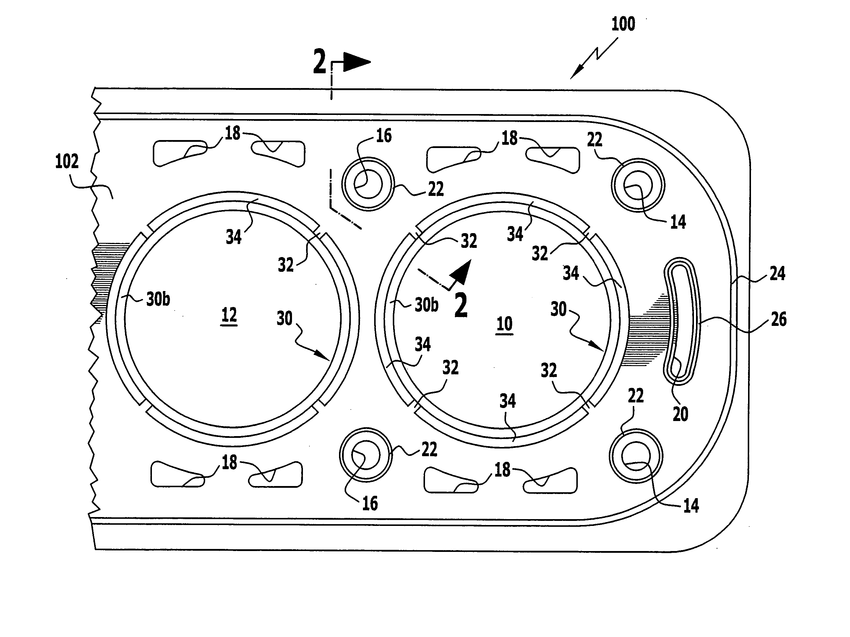
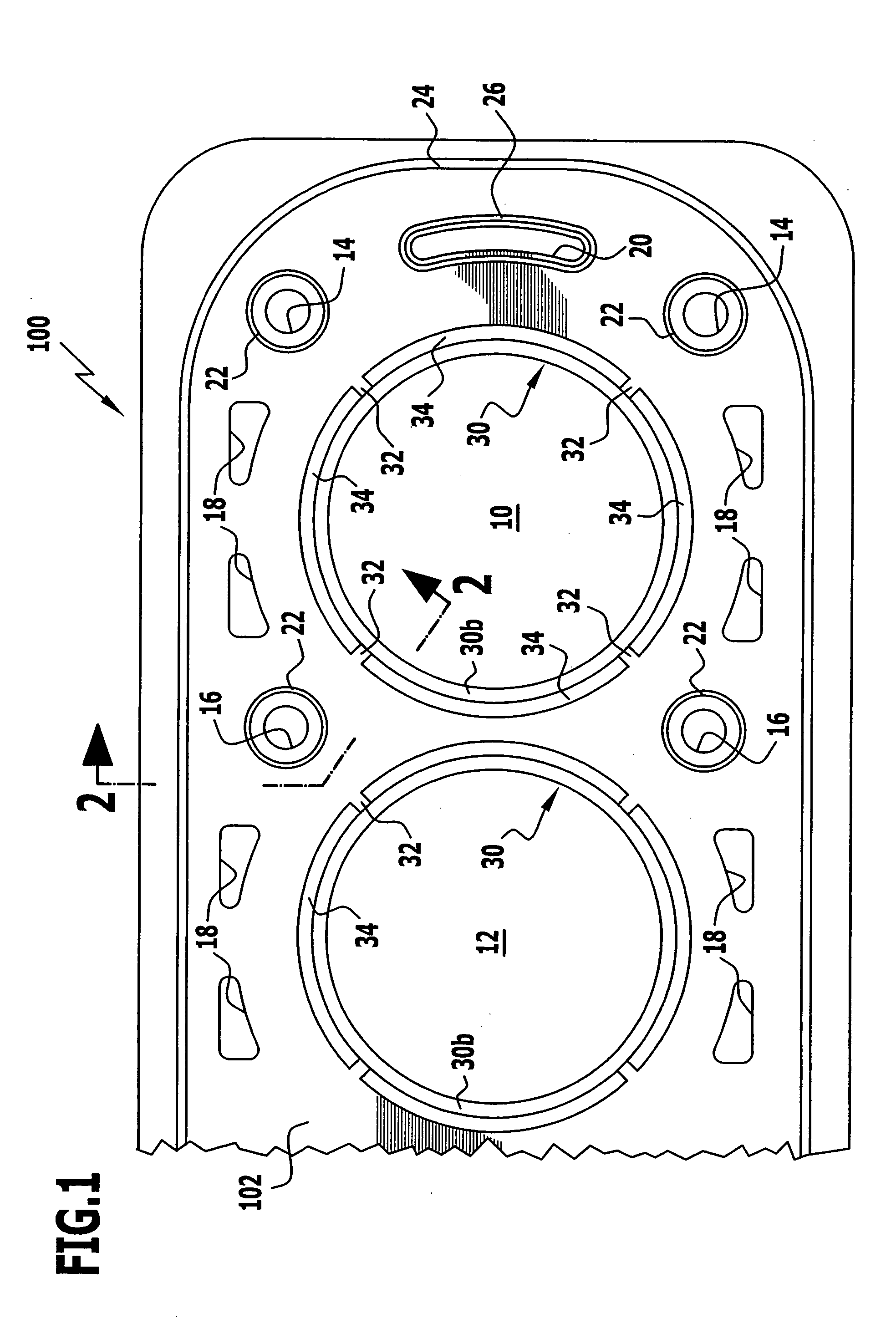
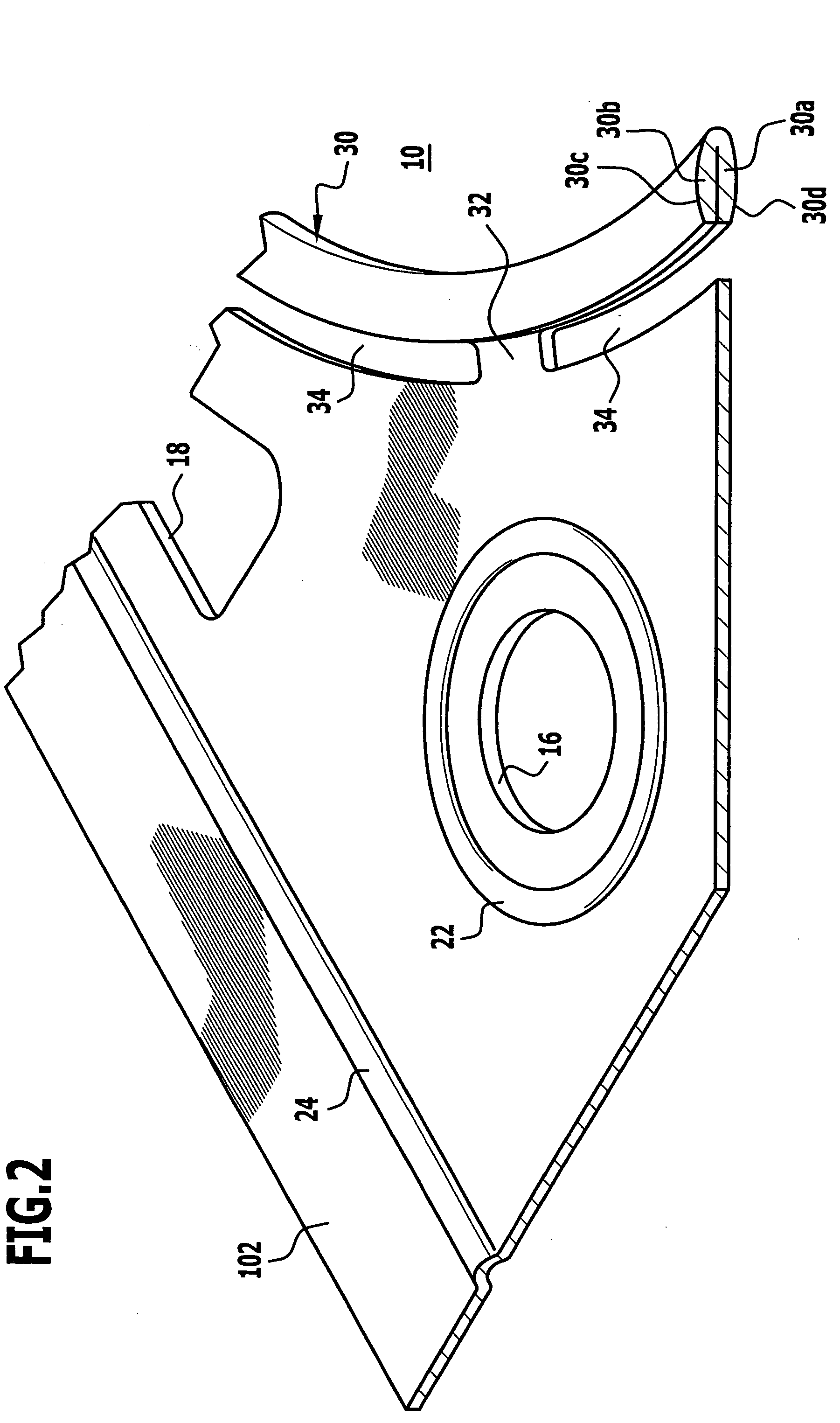
[0013] Finally, for the sake of completeness, it will also be pointed out that substantially metallic cylinder head gaskets with combustion chamber through-openings enclosed by ring-shaped elements of spherical cross section are known from DE-195 20 695-C1 of Elring Klinger GmbH and from U.S. Pat. No. 6,499,743. However, these known ring-shaped elements of spherical cross section are so-called stoppers, which are formed on a middle layer of a three-layer gasket and are to prevent excessive flattening of sealing beads which were stamped in the two outer sheet steel layers of the gasket and enclose the combustion chamber through-openings. However, in these spherical stoppers the crests of the convex surfaces of each stopper always lie exactly one over the other (in a plan view of the gasket plate), quite apart from the fact that according to the drawings of the two above-mentioned documents the sheet metal layers from which the stoppers were formed have such a large sheet thickness that even small tilting movements of the stoppers during operation of the engine appear totally impossible.
[0015] The above-explained sliding movements of the engine component sealing surfaces relative to one another could result in sliding movements occurring between the engine component sealing surfaces and the sealing element according to the invention, even if the latter is always pressed sealingly against the engine component sealing surfaces. Frictional wear which might result from such sliding movements could, however, prove disadvantageous. When a cylinder head gasket according to the invention is designed so that the sealing element according to the invention rests directly against the engine component sealing surfaces of cylinder head and engine block when the gasket is installed, it is, therefore, recommended that the thickness and the compressive strength of the sealing element as well as its material be adapted to the specified materials and possibly to the locally varying stiffnesses of the engine component sealing surfaces and to the specified tightening torque of the cylinder head screws, so that upon occurrence of the movements of the engine component sealing surfaces relative to one another during operation of the engine (parallel to the plane defined by the sealing gap and perpendicular thereto) the sealing element does at least substantially only roll on and not slide on the engine component sealing surfaces. In all areas of the sealing element and at each point in time during operation of the engine the pressing forces between the engine component sealing surfaces and the sealing element are then sufficiently large to ensure overall and always a frictionally engaged coupling of the sealing element to the engine component sealing surfaces and to thus avoid sliding movements resulting in frictional wear.

Problems solved by technology

With a given engine, for which, for example, a three-layered cylinder head gasket has hitherto been used, this results in thicker metal sheets having to be used for gaskets with a smaller number of sheet metal layers, because an otherwise necessary decreasing of the sealing gap dimension would necessitate structural changes to the engine itself, which is not accepted by the manufacturer of the engine.
However, a bead in a thicker sheet metal layer must have a greater width (in section perpendicular to the longitudinal direction of the bead) in order to have the same elastic deformation characteristics as a bead formed in a thinner metal sheet, and as the through-openings to be sealed by sealing elements in cylinder head gaskets designed for modern engines often lie very close to one another, in many cases wider beads cannot be realized owing to lack of space.

Method used


Image

  • Cylinder head gasket
  • Cylinder head gasket
  • Cylinder head gasket

Examples


second embodiment

[0047]FIG. 4 shows an alternative embodiment of a sealing element according to the invention, again of a combustion chamber sealing element 30′ according to the invention, which is formed by a solid sealing strand 40′ which is not produced by folding. Since this embodiment differs from that according to FIG. 2 only in the design of the sealing strand 40′, the same reference numerals were used in FIG. 4 as in FIG. 2, but with the addition of a prime, and, therefore, a further description of FIG. 4 may be dispensed with. In the manufacture of the second embodiment shown in FIG. 4, the procedure may, for example, be such that after punching a combustion chamber opening 10′ out of the sheet steel layer 102′, an edge portion of the sheet steel layer surrounding the combustion chamber opening is first thickened by upsetting and then provided with the convex surfaces 30c′ and 30d′ in a stamping tool, after which the slots 34′ are punched out so as to leave the web-shaped holding elements 3...

third embodiment

[0049] In the sealing element according to the invention shown in FIGS. 5 and 6, its contours are designed in accordance with the invention but differently and, above all, such that the crests of these contours are laterally offset from each other when the cylinder head gasket is installed and the engine is out of operation.

[0050] In FIGS. 5 and 6 the same reference numerals were used as in FIGS. 1 and 2, but with the addition of two primes, and, therefore, in the following the third embodiment shown in FIGS. 5 and 6 will only be described insofar as this third embodiment differs from the first embodiment according to FIGS. 1 to 3.

[0051] In the third embodiment, too, as will be apparent from FIG. 5, a sealing element 30″ according to the invention was produced by a sheet metal layer 102″ of the cylinder head gasket according to the invention being folded back onto itself around a combustion chamber opening 10″, i. e., the sealing element 30″is again formed by a base portion 30a″ of...


PUM


Abstract

Cylinder head gasket with a ring-shaped metallic sealing element extending around a through-opening of the gasket, wherein, for automatic adaptation to changes in the width of the sealing gap to be sealed by the cylinder head gasket, the sealing element is of such spherical shape in cross section at its sides facing the two main surfaces of the gasket as to result in convex surfaces of the sealing element that face the main surfaces of the gasket and each have a crest, and, in the unpressed state of the gasket, these crests, in cross section perpendicular to the longitudinal center axis of a metallic sealing strand forming the sealing element, are laterally offset from one another in the direction of a gasket plane defined by the gasket so that the spacing of planes running parallel to the gasket plane and tangentially to the convex surfaces of the sealing element varies when these convex surfaces tilt about the longitudinal center axis of the sealing strand.

Description

[0001] The present disclosure relates to the subject matter disclosed in German Application No. 10 2004 054 712.2 of Nov. 12, 2004, which is incorporated herein by reference in its entirety and for all purposes. BACKGROUND OF THE INVENTION [0002] The invention relates to an at least substantially metallic cylinder head gasket with a gasket plate having at least one sheet metal layer and at least one through-opening which, for sealing around the through-opening, is enclosed by a ring-shaped sealing element which is pressed when the cylinder head gasket is installed between engine component sealing surfaces. [0003] The gasket plates of such cylinder head gaskets usually have several such through-openings, namely one or several combustion chamber through-openings for the cylinder or cylinders of the engine, as well as coolant through-openings and oil through-openings. The gasket plate also has screw holes through which there extend cylinder head screws, with which the cylinder head gas...

Claims


Application Information

Patent Timeline
Patent Type & Authority Applications(United States)
IPC IPC(8): F02F11/00
CPCF16J15/0818F16J15/0825F16J2015/0843F16J2015/085F16J2015/0862
Inventor DIEZ, ARMIN
Owner ELRINGKLINGER AG
Learn More