Inkjet printer

a technology of inkjet printer and inkjet printing, which is applied in the direction of printing, etc., can solve the problems of increasing the nozzle surface, increasing the risk of damage to the nozzle film and the water repellent coating thereon, and increasing the risk of nozzle film damage, so as to prevent a bubble

Active Publication Date: 2006-05-18
BROTHER KOGYO KK
View PDF1 Cites 19 Cited by
  • Summary
  • Abstract
  • Description
  • Claims
  • Application Information

AI Technical Summary

Benefits of technology

[0011] The present invention has been developed in view of the above-described situations, and therefore it is an object of the invention to provide an inkjet printer capable of preventing a bubble, as generated in a purging operation during which a purge cap covers a front surface of the printhead, from being introduced into a nozzle upon separation of the purge cap from the front surface after the purging operation.

Problems solved by technology

In such an arrangement, the nozzle surface is brought into frictional contact with the recording medium, and the water repellent coating and the nozzle film tend to be damaged.
Recently, to meet a demand for a higher print rate, the size of the nozzle surface has been increased, thereby further increasing the risk of damage of the nozzle film and the water repellent coating thereon.
Since the cover plate has such a through-hole, ink remaining on the front surface can not be completely removed when the front surface is wiped with a wiper immediately after a purging operation.
Hence, stability can not be assured in ejection performance of the printhead.
However, it takes some time to dissolve the bubbles in the ink, and thus it is necessitated to wait until the time elapse before the next printing is started.

Method used


Image

  • Inkjet printer
  • Inkjet printer
  • Inkjet printer

Examples


first embodiment

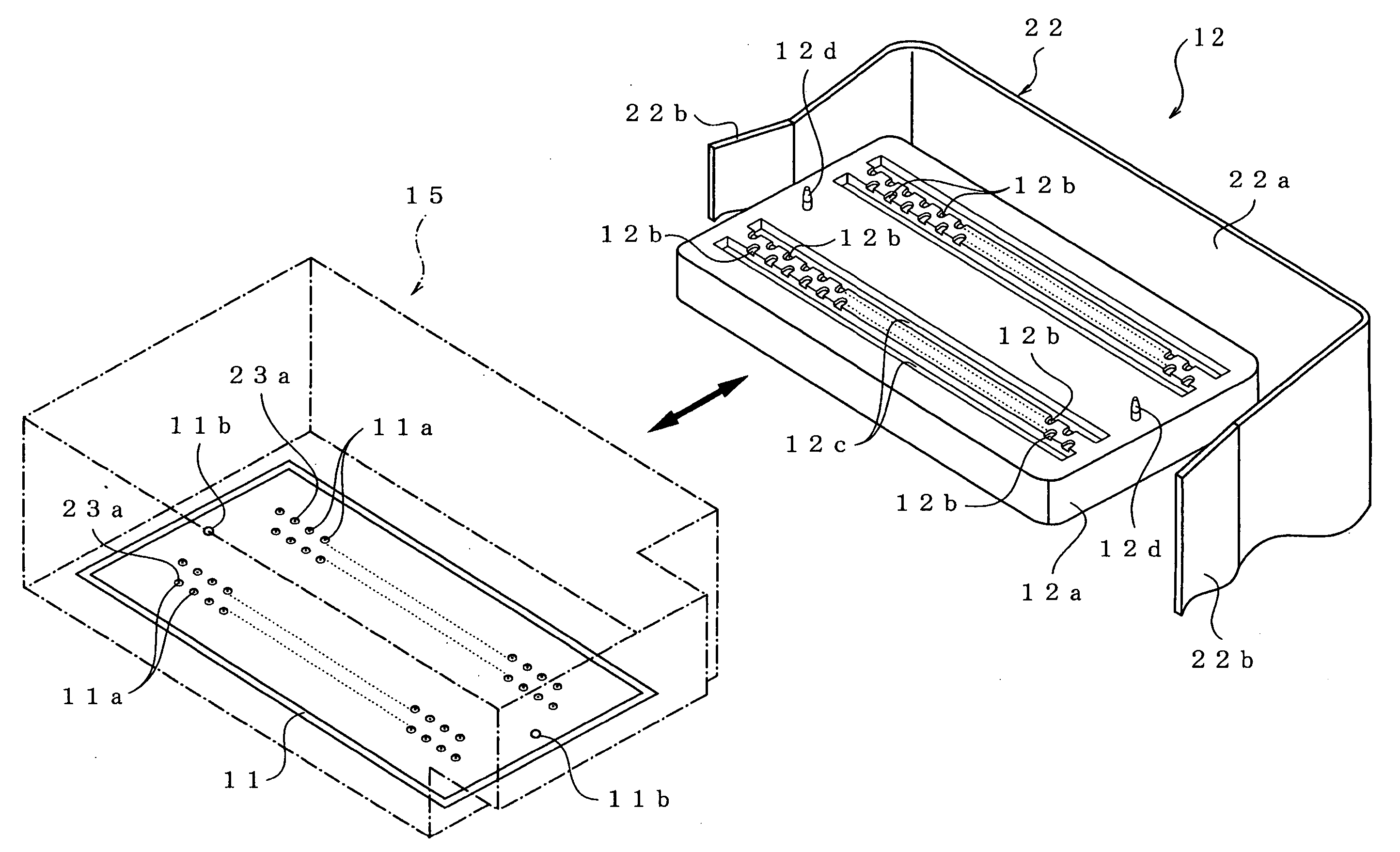
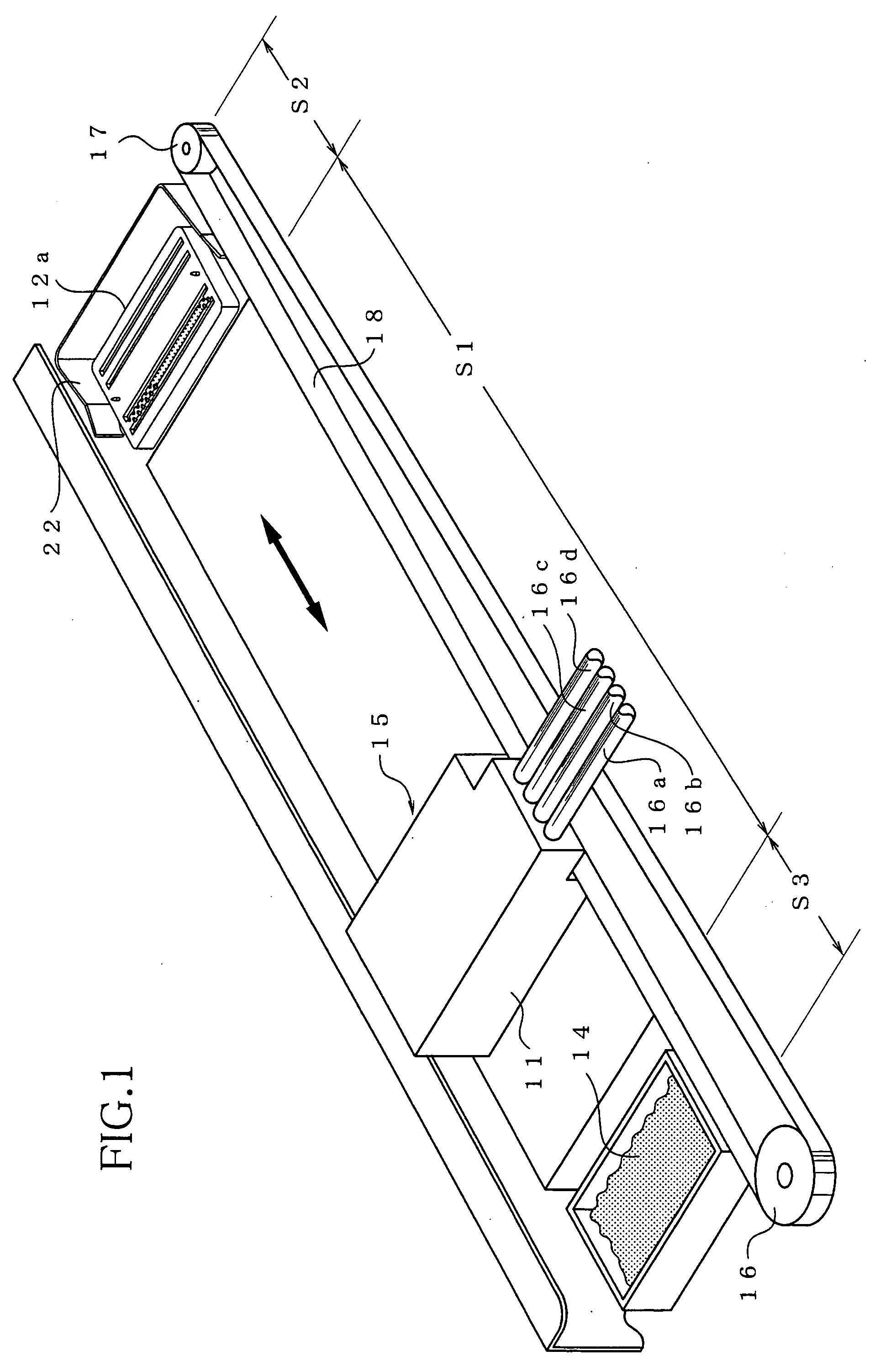
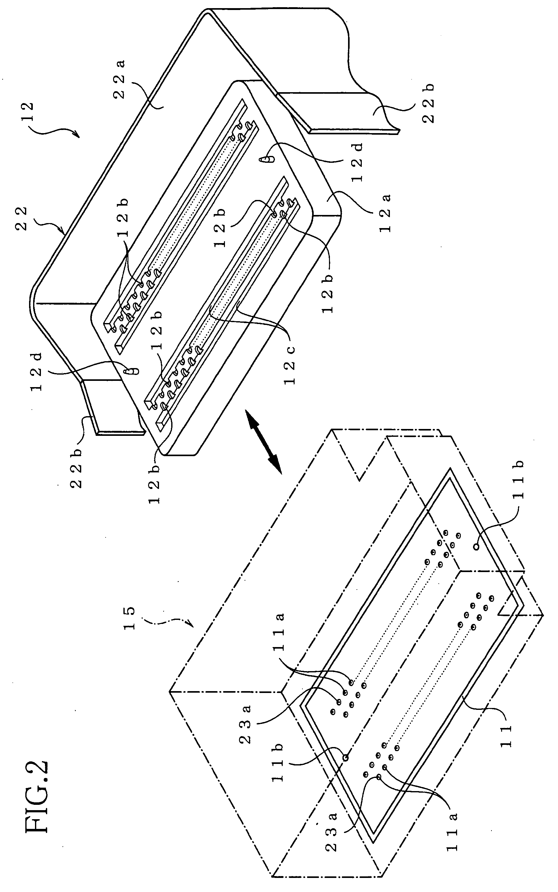
[0037] Referring to FIGS. 1 to 7, there will be described an inkjet printer according to the invention. As shown in FIGS. 1 and 2, the inkjet printer includes an inkjet printhead 11, a maintenance unit 12 that is a purging device, and an ink receiving portion 14. In the inkjet printer, the printhead 11 can be reciprocated across three areas, namely, a recording area S1, a purging area S2, and a flashing area S3. The purging area S2 and the flashing area S3 are on the opposite sides of the recording area S1. The printhead 11 has a plurality of nozzles 11a each for ejecting an ink droplet therefrom onto a recording medium such as a sheet of paper. Printing on the recording medium is performed while the printhead 11 is reciprocated across the recording area S1. A purging operation is performed when the printhead 11 is located at the purging area S2 where the maintenance unit 12 is disposed. The maintenance unit 12 includes a purge cap 12a for receiving ink discharged or sucked from the...

second embodiment

[0066]FIG. 9 is an enlarged perspective view of a part of the purge cap 212a, in which two nozzles are included. A structure of the purge cap 212a is a characterizing portion of the invention. The purge cap 212a has a contact surface on which are formed a plurality of dents 223c into which the respective nozzles 11a open, and a plurality of grooves 212c. Each dent 223c includes a branch groove or recessed portion as a connecting portion 223b, and a through-hole 223a. That is, at the connecting portion 223b, a thickness of the cover plate 223 is reduced. When the front surface of the printhead 211 is covered by the purge cap 212a at a purging area S2, each groove 212c extends alongside one of the nozzle rows so as to communicate connecting portions 223b of the respective dents 223c corresponding to that nozzle row. Each of the grooves 212c is disposed to extend under a substantially longitudinal center of the connecting portions 223b of the dents 223c. In FIG. 9, there are shown two ...

third embodiment

[0076] As seen in FIG. 14 showing a front surface of the printhead, the printhead of the third embodiment does not include a cover plate covering a nozzle film 321A. A plurality of dents 321Aa whose depth is about 5-10 μm are formed on the nozzle film 321A by irradiating the nozzle film 321A with an excimer laser beam.

[0077] By this arrangement, the same effects as the first and second embodiments of the invention can be obtained.

[0078] There will be now described an inkjet printer according to a fourth embodiment of the invention, by referring to FIG. 15. The inkjet printer of the fourth embodiment is different from that of the second embodiment in the structure of the printhead. Only the different part will be described, and the parts or elements corresponding to those of the second embodiment will be denoted by the same reference numerals and description thereof is not provided.

[0079] In the above-described second embodiment, a dent 223c including a through-hole 223a and a conn...


PUM


Abstract

There is disclosed an inkjet printer including: a printhead having a front surface in which is formed at least one nozzle row consisting of a plurality of nozzles from each of which a droplet of ink is ejected; a maintenance unit including a purge cap which receives ink from the nozzles during a purging operation, the purge cap having a contact surface to be brought into contact with the front surface of the printhead, and at least one main channel extending alongside the nozzle row; and a plurality of dents formed on at least one of the contact surface of the purge cap and the front surface of the printhead so as to form, at least when the contact surface is in contact with the front surface, a plurality of branches a part of each of which is in communication with at least one of the nozzles, and another part of each of which is in communication with the main channel.

Description

INCORPORATION BY REFERENCE [0001] The present application is based on Japanese Patent Applications Nos. 2004-330488 and 2004-330489, both filed on Nov. 15, 2004, the contents of which are incorporated herein by reference. BACKGROUND OF THE INVENTION [0002] 1. Field of the Invention [0003] The present invention relates to an inkjet printer. [0004] 2. Description of Related Art [0005] As a kind of recording apparatus for recording information on a recording medium such as a sheet of paper, there is known an inkjet printer that ejects ink droplets onto a recording medium to record information. Such an inkjet printer includes an actuator, a printhead, and a maintenance unit including a purge cap. The printhead has ink passages formed therein, and a nozzle surface where a plurality of nozzles for ejecting ink droplets therefrom are arranged. In the inkjet printer, the printhead is movable between a recording area and a purge area adjacent to the recording area. The printhead performs pri...

Claims


Application Information

Patent Timeline
Patent Type & Authority Applications(United States)
IPC IPC(8): B41J2/165
CPCB41J2/16508B41J2/16532
Inventor KATAYAMA, NAOKI
Owner BROTHER KOGYO KK
Why Eureka
Try Eureka