Optical element and display device using the same

a technology of optical elements and display devices, applied in the field of optical elements, can solve the problems of deteriorating image quality and lowering the transmittance of light, and achieve the effect of avoiding deterioration of image quality

Active Publication Date: 2006-05-18
PANASONIC LIQUID CRYSTAL DISPLAY CO LTD +1
View PDF10 Cites 37 Cited by
  • Summary
  • Abstract
  • Description
  • Claims
  • Application Information

AI Technical Summary

Benefits of technology

[0039] It then becomes possible to provide the optical element, or the display device using this optical element, which limit transmissions of light at a predetermined azimuth angle and in a predetermined polar angle ra

Problems solved by technology

As a result, the louver film owns the following problem.
That is, moire may occur between a pixel array of display elements and the periodic structure of the louver film, so that an image quality is deteriorated.
Further, since the louver

Method used


Image

  • Optical element and display device using the same
  • Optical element and display device using the same
  • Optical element and display device using the same

Examples


embodiment 1

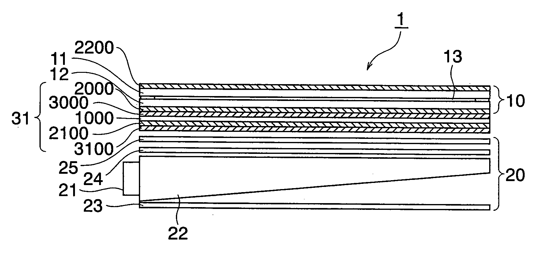
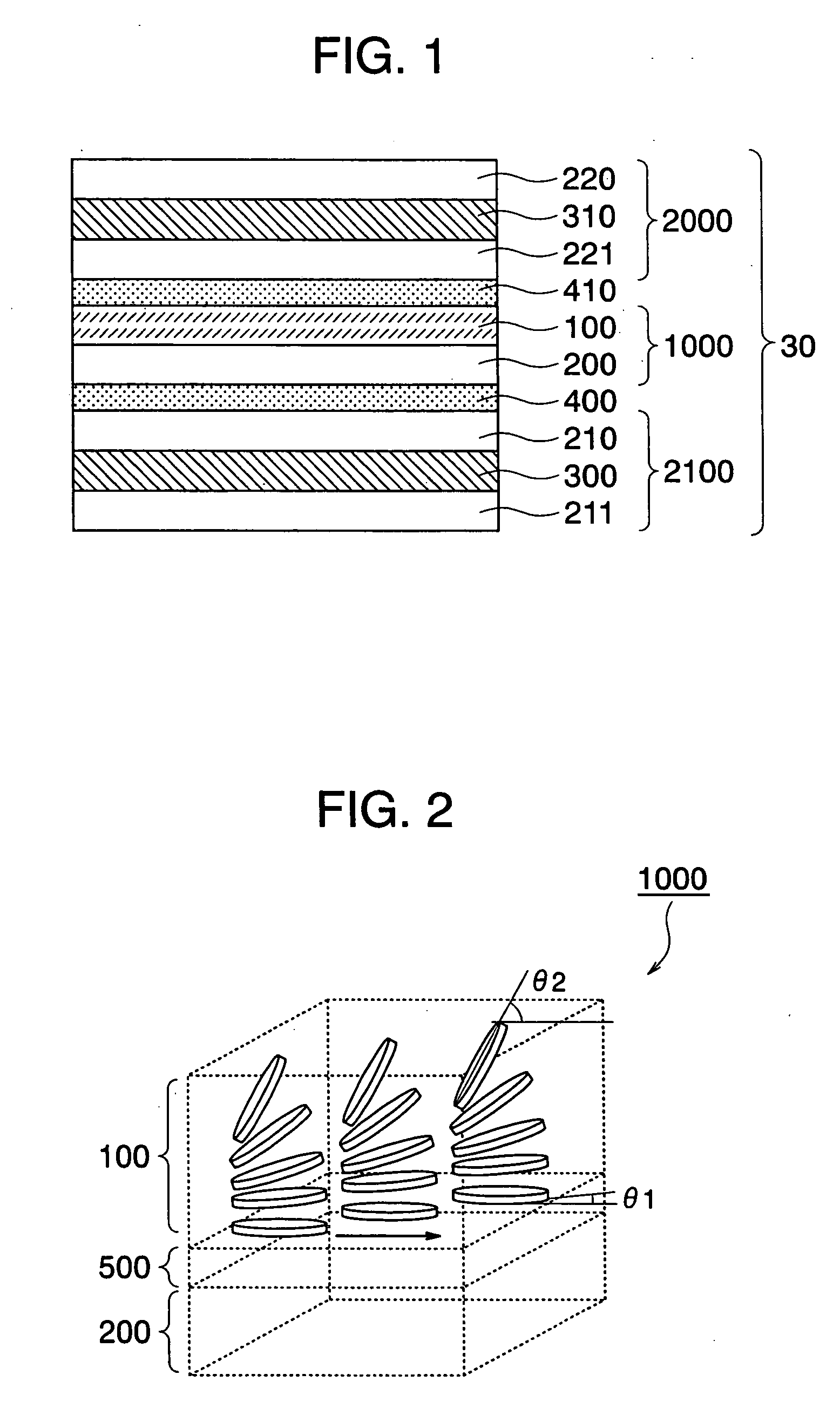
[0085]FIG. 1 is a sectional view for indicating a portion of an optical element according to an embodiment 1 of the present invention. This optical element is capable of reducing an amount of light transmittance in specific azimuth and a specific view angle range. In the case that the above-described optical element is employed in a display device, this optical element is capable of limiting a view angle within which an image on a screen attached to the element can be seen by an operator. In this specification, an optical element having such a function will be referred to as a “view angle limiting element” hereinafter.

[0086] A view angle limiting element 30 of the embodiment 1 is constructed in such a manner that a liquid crystal film 1000 containing a discotic liquid layer 100 is stacked between a first polarizing film 2000 and a second polarizing film 2100.

[0087] A polarizer transmits therethrough one of linearly polarized light components within light entered to the own polarli...


PUM


Abstract

An optical element is arranged in such a manner that a screen thereof can be hardly observed from a predetermined direction, and a deterioration of an image quality caused by moire does not occur. The optical element is constituted by a first polarizing layer, a second polarizing layer, and a liquid crystal layer arranged between these two polarizing layers. In the optical element, absorption axes of the first polarizing layer and the second polarizing layer are located parallel to each other; the liquid crystal layer is made of hybrid-aligned discotic liquid crystal; and an alignment axis of the liquid crystal layer is located parallel to, or perpendicular to both absorption axes of the first polarizing layer and of the second polarizing layer.

Description

BACKGROUND OF THE INVENTION [0001] 1. Field of the Invention [0002] The present invention relates to an optical element capable of varying view angles of a screen in display device, and a display device equipped with such optical element. [0003] 2. Description of the Related Art [0004] As to screens of display devices, wide view angles are required which are effective in such a case that these screens are observed by a large number of viewers, and in contrast, narrow view angles are required in order that contents of screens are peeped by a third party, namely, various conditions are required for these screens of the display devices in response to use circumstances thereof. [0005] As optical elements capable of narrowing view angles of screens of display devices, such a film that optical absorption layers and transparent layers are alternately arranged in a louver shape (will be referred to as “louver film” hereinafter) has been practically available. [0006] Louver films have been c...

Claims


Application Information

Patent Timeline
IPC IPC(8): G02F1/1335
CPCG02F1/1323G02F1/133524G02F1/133632G02F1/13471G02F1/1335G09F9/35G02F1/133
Inventor ADACHI, MASAYAITOU, OSAMUKOMURA, SHINICHI
Owner PANASONIC LIQUID CRYSTAL DISPLAY CO LTD
Why Eureka
Try Eureka