Vertically aligned liquid crystal display

a liquid crystal display and vertical alignment technology, applied in non-linear optics, instruments, optics, etc., can solve problems such as light leakage, and achieve the effect of minimizing light leakage and high contras

Active Publication Date: 2006-05-18
LG CHEM LTD
View PDF7 Cites 8 Cited by
  • Summary
  • Abstract
  • Description
  • Claims
  • Application Information

AI Technical Summary

Benefits of technology

[0009] An aspect of the present invention is to solve at least the above problems and / or disadvantages and to provide at least the advantages described below. Accordingly, an aspect of the present invention is to provide a VA-LCD with high contrast at the front viewing direction and the declination viewing direction by minimizing leakage of light of a black state.

Problems solved by technology

However, a VA-LCD with −C plate compensation film has a problem that leakage of light is caused at a tilt angle because the −C plate can not completely compensate the black state.

Method used


Image

  • Vertically aligned liquid crystal display
  • Vertically aligned liquid crystal display
  • Vertically aligned liquid crystal display

Examples


embodiment 1

[0065] Configuration of the First VA-LCD

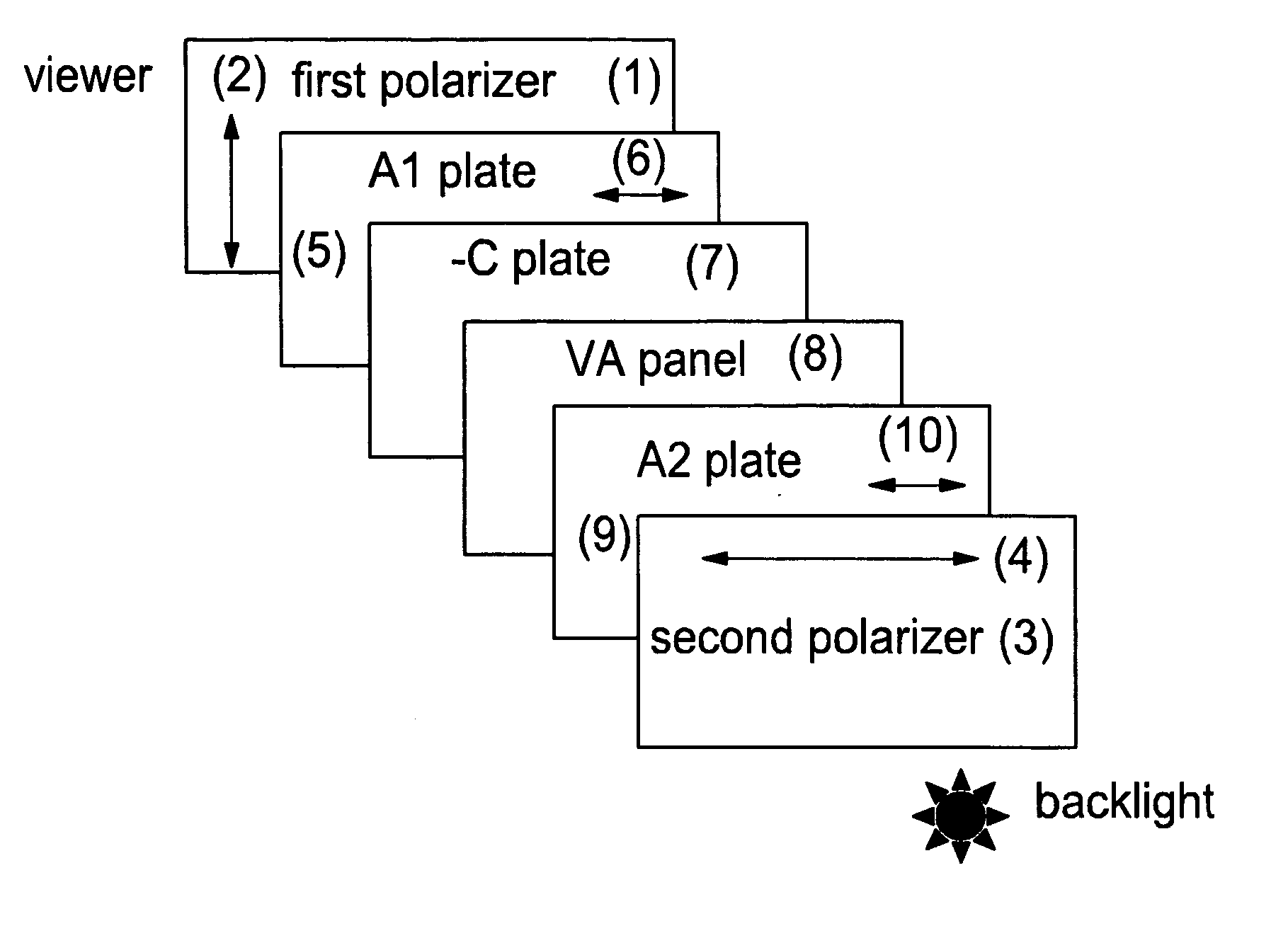
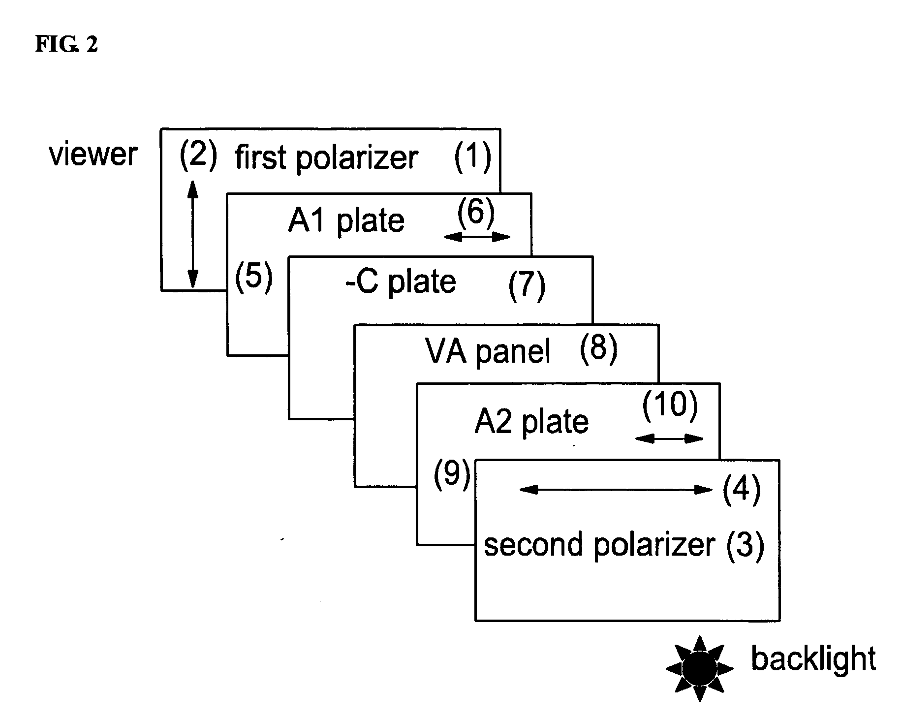
[0066] Referring to FIG. 2, a VA-panel comprises a plurality of VA liquid crystal cells 8 having a cell gap of 2.9 μm where the liquid crystal cell is filled with liquid crystals having a pre-title angle of 90 degrees, a dielectric anisotropy Δε is −4.9, and a birefringence Δn is 0.099. The −C plate 7 is made of a liquid crystal film, and has a thickness retardation value Rth of −240 nm for a wavelength of 550 nm. The A1 plate 5 being close to the first polarizer 1 has an in-plane retardation value Rin of 90 nm, and the A2 plate 9 being close to the second polarizer 3 has an in-plane retardation value Rin of 340 nm. The inner protective films of the first polarizer 1 and the second polarizer 3 are made of triacetate cellulose film with a thickness of 40 μm and a thickness retardation value of −28 nm.

[0067] When using white light, contrast characteristics over 0 to 80 degrees with respect to all azimuth angles is shown in FIG. 6. In FIG. 6, t...

embodiment 2

[0069] Configuration of Second VA-LCD

[0070] Referring to FIG. 3, a VA-panel comprises a plurality of liquid crystal cells 8 filled with liquid crystals with a cell gap of 2.9 μm, a pre-title angle of 90 degrees, a dielectric anisotropy Δε is −4.9, and a birefringence Δn is 0.099. The −C plate 7 is made of a liquid crystal film, has a thickness retardation value Rth of −180 nm for a wavelength of 550 nm. The A1 plate 5 being close to the first polarizer 1 has an in-plane retardation value Rin of 120 nm, and the A2 plate 9 being close to the second polarizer 3 has an in-plane retardation value Rin of 80 nm. The inner protective films of the first polarizer 1 and the second polarizer 3 are made of TAC film with a thickness of 80 μm and a thickness retardation value of −56 nm.

[0071] When using white light, contrast characteristics over 0 to 80 degrees with respect to all azimuth angles are shown in FIG. 7. In FIG. 7, the contrast characteristic over 0 to 80 degrees with respect to all...

embodiment 3

[0072] Configuration of Third VA-LCD

[0073] Referring to FIG. 4, a VA-panel comprises a plurality of liquid crystal cells 8 filled with liquid crystals with a cell gap of 2.9 μm, a pre-title angle of 90 degrees, a dielectric anisotropy Δε is −4.9, and a birefringence Δn is 0.099.

[0074] The bi-axial retardation film 11 being close to the first polarizer 1 has an in-plane retardation value Rin of 70 nm and a thickness retardation value, Rth of −140 nm. The +A plate 9 being close to the second polarizer 3 has an in-plane retardation value Rin of 30 nm. The inner protective film of the first polarizer 1 is made of a TAC film with a thickness of 40 μm and its thickness retardation value is −28 nm. The inner protective film of the second polarizer 3 is made of TAC film and has a thickness of 80 μm and a thickness retardation value of −56 nm.

[0075] When using white light, contrast characteristics over 0 to 80 degrees with respect to all azimuth angles is shown in FIG. 8.

[0076] In FIG. 8...


PUM

PropertyMeasurementUnit
wavelengthaaaaaaaaaa

Abstract

Disclosed is a vertically aligned liquid crystal display (VA-LCD) having wider viewing angle and having high contrast at the right angle and tilt angles. According to one embodiment of the present invention, the VA-LCD having liquid crystal cells in which liquid crystals with a negative dielectric anisotropy are filled and which is provided between a first polarizer and a second polarizer, whose absorption axises are perpendicular to each other, includes a sheet of +A plate and a sheet of −C plate, disposed between the first polarizer and the liquid crystal cells; and a sheet of +A plate disposed between the second polarizer and the liquid crystal cells, wherein an optical axis of the +A plate near the first polarizer is perpendicular to the absorption axis of the first polarizer, and an optical axis of the +A plate near the second polarizer is perpendicular to the absorption axis of the second polarizer. According to another embodiment of the present invention, a VA-LCD having liquid crystal cells in which liquid crystals with a negative dielectric anisotropy are filled and which are disposed between a first polarizer and a second polarizer, whose absorption axises are perpendicular to each other, includes a bi-axial retardation film disposed between the first polarizer and the liquid crystal cells, and a sheet of +A plate disposed between the second polarizer and the liquid crystal cells, wherein an optical axis of the bi-axial retardation film near the first polarizer is perpendicular to the absorption axis of the first polarizer, and an optical axis of the +A plate is parallel with the absorption axis of the second polarizer.
Accordingly, the configuration of FIG. 11 has not an advantage more than the configurations of FIG. 2 and 3 in aspects of manufacturing process and cost. The VA-LCD according to the present invention has an advantage that viewing angle compensation effect is enhanced due to the arrangement of the viewing angle compensation films, thereby implementing the wider viewing angle characteristic.

Description

CROSS-REFERENCE TO RELATED APPLICATIONS [0001] This application claims the benefit under 35 U.S.C. § 119(a) of Korean Application No. 2004-0092552, filed on Nov. 12, 2004, in the Korean Intellectual Property Office, the entire disclosure of which is incorporated herein by reference. BACKGROUND OF THE INVENTION [0002] 1. Field of the Invention [0003] The present invention relates to a vertically aligned liquid crystal display (hereinafter, referred as “VA-LCD”). More particularly, the present invention relates to a VA-LCD in which contrast ratio in the front viewing direction and tilt viewing directions is improved by using a viewing angle compensation film. [0004] 2. Description of the Related Art [0005] There are two primary reasons of degradation of a viewing angle of VA-LCDs: first one is the viewing angle dependence of a perpendicular polarizer and second one is the viewing angle dependence of birefringence of a VA-LCD panel. [0006] U.S. Pat. No. 4,889,412 disclosed a VA-LCD usi...

Claims


Application Information

Patent Timeline
Patent Type & Authority Applications(United States)
IPC IPC(8): G02F1/1335G02F1/1337
CPCG02F1/13363G02F1/133634G02F1/1393G02F1/1335
Inventor JANG, SOO-JINJEON, BYOUNG-KUNBELYAEV, SERGEYCHANG, JUN-WON
Owner LG CHEM LTD
Why Eureka
Try Eureka