Linear motion guide unit

a technology of motion guide and guide roller, which is applied in the direction of bearings, shafts and bearings, bearings, etc., can solve the problems of unsuitable slender rollers, more failure of recirculating performance, and more problems such as the inability to lean in the rolling posture, so as to improve the mechanical strength and reduce the sliding resistance. , the effect of high soakability

Active Publication Date: 2006-05-18
NIPPON THOMPSON
View PDF3 Cites 7 Cited by
  • Summary
  • Abstract
  • Description
  • Claims
  • Application Information

AI Technical Summary

Benefits of technology

[0011] The present invention has for its primary object to overcome the shortcomings as stated earlier, and to provide a linear motion guide unit constructed to render it suitable for slender rollers, in which even rollers small in diameter are tough to lean while there is no possibility a spacer piece to provide a turnaround passage affects negatively the recirculating performance of the rollers, thereby ensuring that the rollers are guided smoothly over a long-lasting service life with steady maintenance-free condition for lubricant replenishment. More particularly, the present invention provides a linear motion guide unit in which the spacer piece to define the turnaround passage has a lubricant reservoir to ensure copious lubrication onto the rollers, and a sleeve to define a return passage in a slider is upgraded in mechanical strength, the sleeve being made of a tubular composition comprised of a tubular skeleton partially cutaway to have windows therein, and a cellular molded member, the cellular molded member being impregnated in advance with lubricant to fill cells or pores with the lubricant, and followed by fit into the windows to make the tubular composition into a composite construction, thereby establishing maintenance-free operation to ensure proper lubrication on a recirculating circuit for the rollers.
[0012] The present invention is concerned with a linear motion guide unit comprising an elongated guide rail having a lengthwise raceway surface thereon, and a slider movable lengthwise of the elongated guide rail, the slider being comprised of a carriage made therein with a second raceway surface in opposition to the first raceway surface and a return passage extending in parallel with a load race defined between the first and second raceway surfaces, end caps mounted on lengthwise opposite ends of the carriage and made therein with turnaround passages connecting the load race with the associated return passage, and more than one roller allowed to roll through a recirculating circuit composed of the load race, the return passage and the turnaround passages, wherein the end caps are each comprised of an end cap major body to make a radially outside curved surface of the turnaround passage and guide surfaces extending along widthwise opposite edges of the radially outside curved surface to make a sliding-contact with axially opposite ends of the roller, and a spacer having an outside surface to make a radially inside curved surface of the turnaround passage after having fitted into the end cap major body, the outside surface of the spacer having thereon some holes, which have functions of lubricant reservoirs, prevention of distortion caused in the molded spacer pieces, and ejector pinholes.
[0022] With the linear motion guide unit in which the tubular composition to define the return passage is composed of a tubular skeleton having therein windows, and cellular members to fit into the windows in the tubular skeleton, moreover, the tubular composition is enhanced in mechanical strength for itself while the cellular members impregnated with lubricant are high in capability of soaking up and retaining oily lubricant or grease in cells or pores. Thus, the rolling elements, when coming into rolling-contact with the cellular member while rolling through the return passage, are applied with lubricant film, which would be transferred to the circulating circuit as the rolling elements roll thorough the circuit, thereby establishing maintenance-free operation to ensure proper lubrication on a recirculating circuit for the rolling circuit.
[0023] The linear motion guide unit constructed according to the present invention, consequently, may serve lubricating function with efficiency in harshest working environment including high temperature, and so on, as well as in clean atmosphere where there are any constraint on the application of lubricant. Further, the linear motion guide unit of the present invention is better for reducing sliding resistance in the load-carrying race in the linear motion guide unit that is high in operating speed and reciprocating cycle, even with no need of maintenance for periodic lubricant replenishment.

Problems solved by technology

Correspondingly, the linear motion guide units built in the advanced machinery are also challenged to keep the consumption of lubricant to a minimum, along with keeping linear motion guide units virtually maintenance free.
With the linear motion guide unit in which cylindrical rollers are selected as the rolling elements, nevertheless, alignment problems to guide rollers in good rolling order without leaning in rolling posture are more encountered, compared with the construction using balls.
H05-209617 recited earlier is favorable for the cylindrical roller larger in diameter, but unsuited for the slender roller, which is easier to lean to get more failure in recirculating performance.
Thus, the prior linear motion guide unit would involve the alignment problem where the cylindrical rollers are prone to lean to get more failure in recirculating performance that would ensure the steady recirculation to the rollers for long-lasting service period with maintenance-free condition for lubricant replenishment.
Thus, the prior linear motion guide units of the sort in which the return passage is made of only sintered resinous member of cellular geometry, because there is a scarcity of mechanical stiffness in the sintered resinous member, have been unsuited for making certain of smooth recirculation of the rollers.

Method used


Image

  • Linear motion guide unit
  • Linear motion guide unit
  • Linear motion guide unit

Examples


Embodiment Construction

[0038] The linear motion guide unit according to the present invention is adapted for use in any relatively sliding components in machinery as diverse as precision machines, measurement / inspection instruments, medical instruments, micromachines, machine tools, and so on.

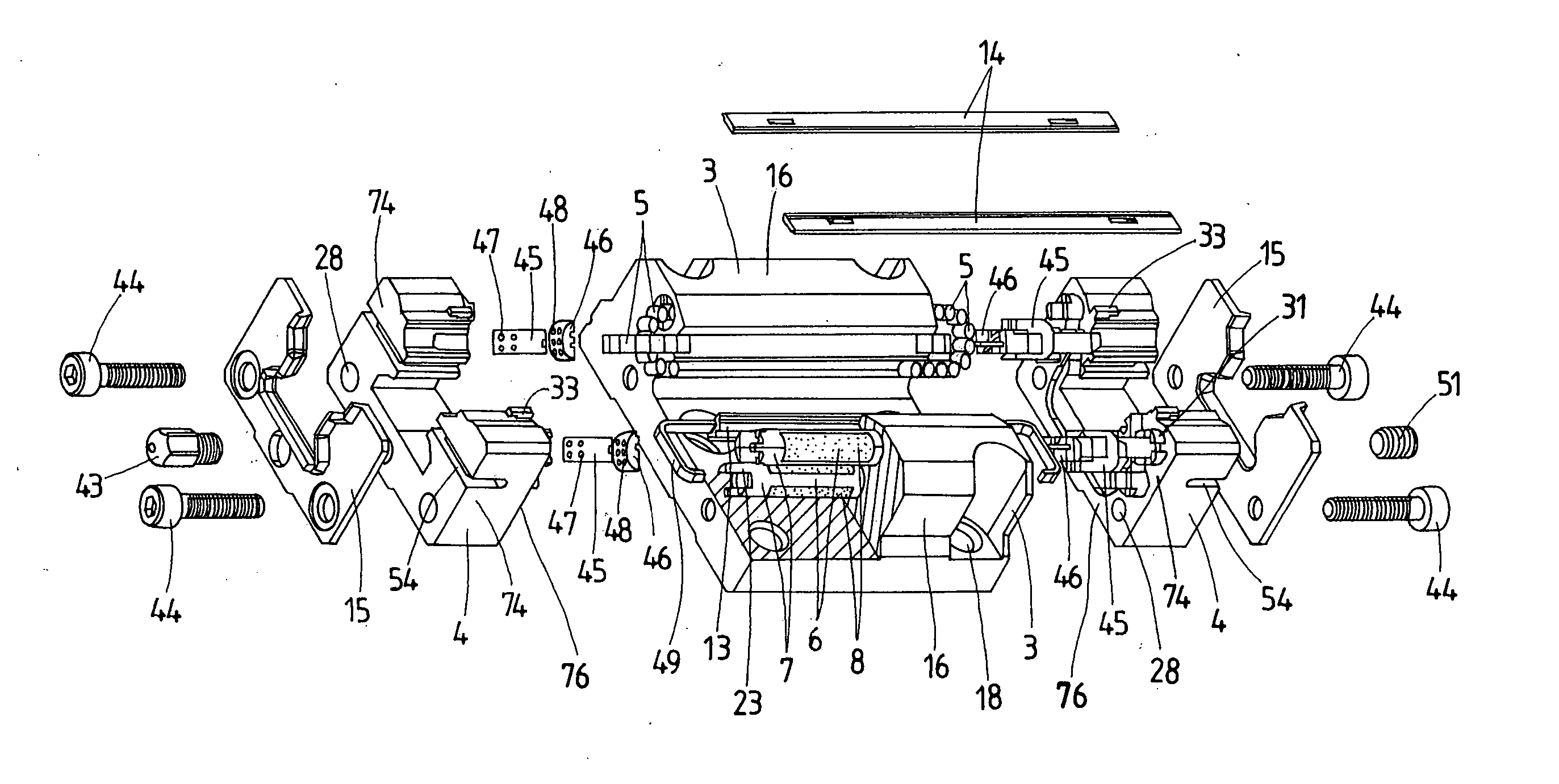
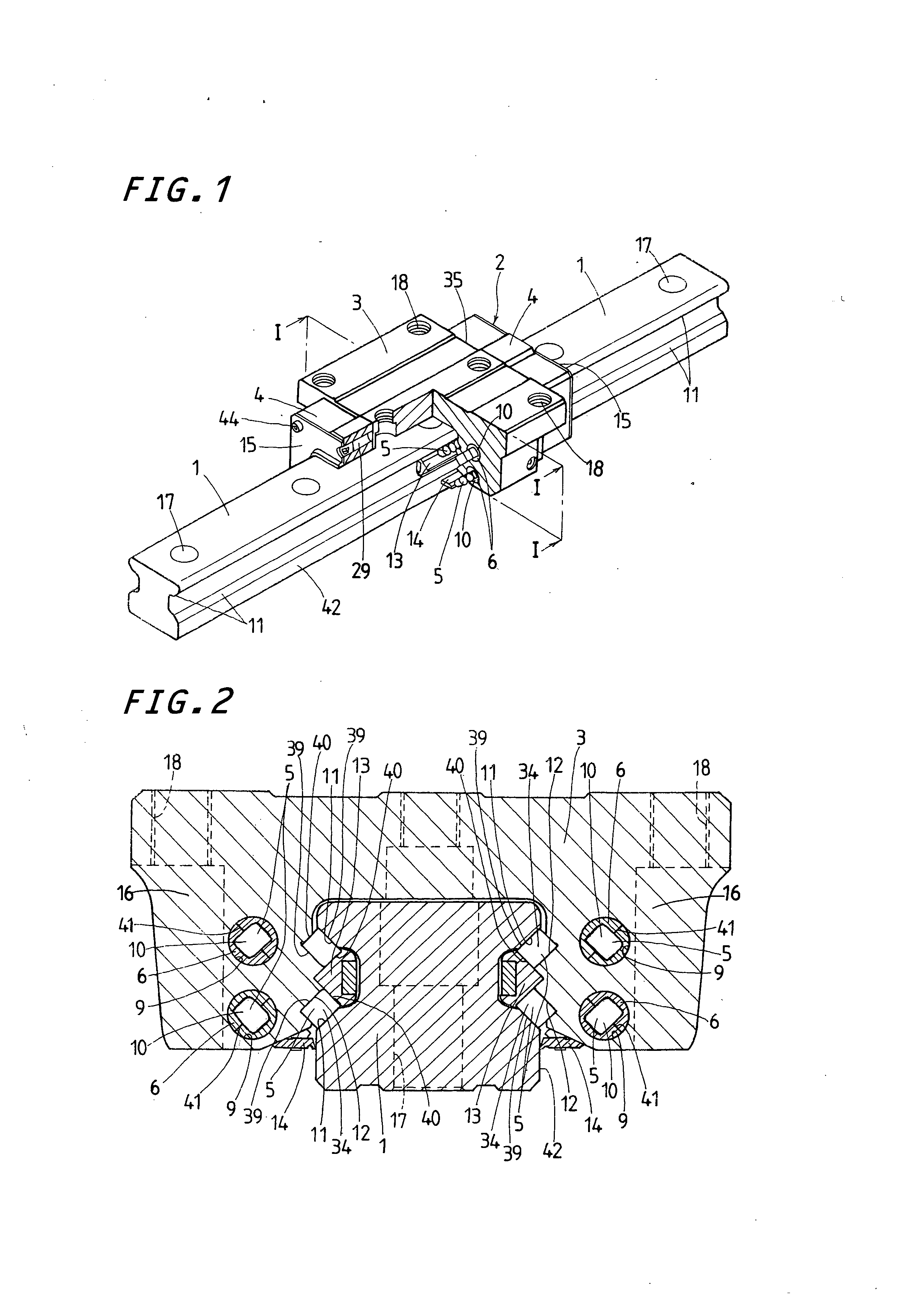
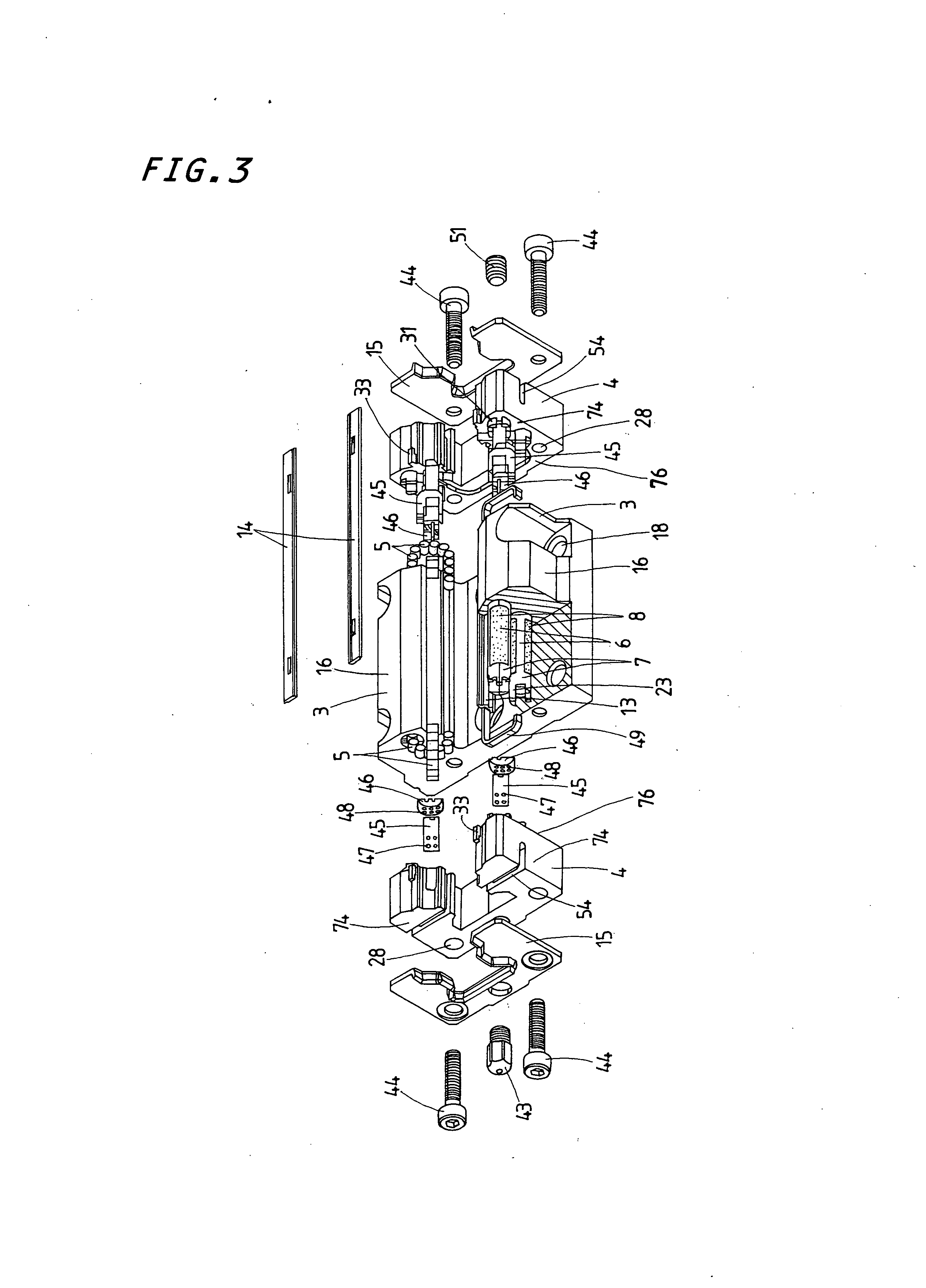
[0039] Referring now in detail to the drawings, the linear motion guide unit according to the present invention will be explained below. The linear motion guide unit of the present invention is composed of a roller-bearing type which is finding in recent years increased application. The present invention is envisaged developing especially the linear motion guide unit having rollers whose diameter is comparatively small, which can cope with demand to work over long-lasting operation even with maintenance-free condition for lubricant replenishment.

[0040] The linear motion guide unit of the present invention is composed of the roller-bearing type whose rolling element is a roller 5, and envisaged further developing th...


PUM


Abstract

A linear motion guide unit suitable for slender rollers, in which a tubular composition to define a return passage as well as a spacer piece to make a turnaround improve in property of retaining lubricant therein, thereby helping accomplish long-lasting service operation for lubrication. The tubular composition is composed of a tubular skeleton and a cellular member that fits into a window cut in the tubular skeleton. An end cap is comprised of an end cap major body, and two classes of spacer pieces nested in the end cap major body to define the turnaround passages. The spacer pieces of two classes are each made around outside surfaces thereof with some circular holes, which have functions of lubricant reservoirs, prevention of distortion or deformation caused in the molded spacer pieces, and ejector pinholes used to extract the molded spacer pieces out of the mold.

Description

FIELD OF THE INVENTION [0001] The present invention relates to a linear motion guide unit comprised of an elongated guide rail, and a slider that is allowed to move on the elongated guide rail relatively to the guide rail by virtue of more than one rolling element. BACKGROUND OF THE INVENTION [0002] The recently remarkable development in mechatronics technology extensively requires various sorts of linear motion guide units, especially, linear motion guide units of the type using rolling elements of cylindrical roller, which are also required to meet with the maintenance-free operation where there is no need of lubricant replenishment for considerably long service life even under severe operating conditions. Most conventional linear motion guide units are composed of an elongated guide rail and a slider that moves relatively to the guide way by virtue of more than one rolling element, which is allowed to roll through a recirculating circuit that is made up of a load-carrying race de...

Claims


Application Information

Patent Timeline
Patent Type & Authority Applications(United States)
IPC IPC(8): F16C29/06F16C33/10
CPCF16C33/6648F16C29/0609F16C29/0611F16C29/065
Inventor KUWABARA, HIDEKI
Owner NIPPON THOMPSON
Why Eureka
Try Eureka