Instrumented antifriction bearing and electrical motor equipped therewith

an anti-friction bearing and instrument technology, applied in the field of anti-friction bearings, can solve the problems of insufficient axial compactness of this type of anti-friction bearing, inability to operate satisfactorily, and inability to integrate, so as to achieve enhanced precision, precise detection, and satisfactory axial compactness

Inactive Publication Date: 2006-05-18
AB SKF
View PDF64 Cites 55 Cited by
  • Summary
  • Abstract
  • Description
  • Claims
  • Application Information

AI Technical Summary

Benefits of technology

[0009] In some embodiments, the instrumented antifriction bearing device may include a rotating portion, a nonrotating portion and an assembly for detecting rotation parameters. An assembly for detecting rotation parameters may include an encoder and a sensor. A sensor may be integrated with the nonrotating portion and may include a sensor unit. A sensor may include at least one microcoil with a substantially flat winding. A microcoil may be positioned on a support of a circuit mounted in the sensor unit of the nonrotating portion so that the microcoil may be axially opposite the encoder. This may provide satisfactory axial compactness.
[0010] In one embodiment, the device may include a plurality of substantially radial coplanar reception microcoils, which may allow substantially precise detection. In certain embodiments, the device may include a plurality of reception microcoils positioned on a plurality of parallel radial planes. An increased number of reception coils may provide enhanced precision.

Problems solved by technology

However, this type of encoder cannot operate at temperatures above 120°.
In addition, the sensor and the encoder do not operate satisfactorily if they are subjected to high intensity external magnetic fields, for example the magnetic fields induced by the coils of the stator of electric motors and / or by the electromagnetic brake built into the motors.
Finally, the axial compactness of this type of antifriction bearing is not optimal and is not easy to incorporate.

Method used


Image

  • Instrumented antifriction bearing and electrical motor equipped therewith
  • Instrumented antifriction bearing and electrical motor equipped therewith
  • Instrumented antifriction bearing and electrical motor equipped therewith

Examples


Embodiment Construction

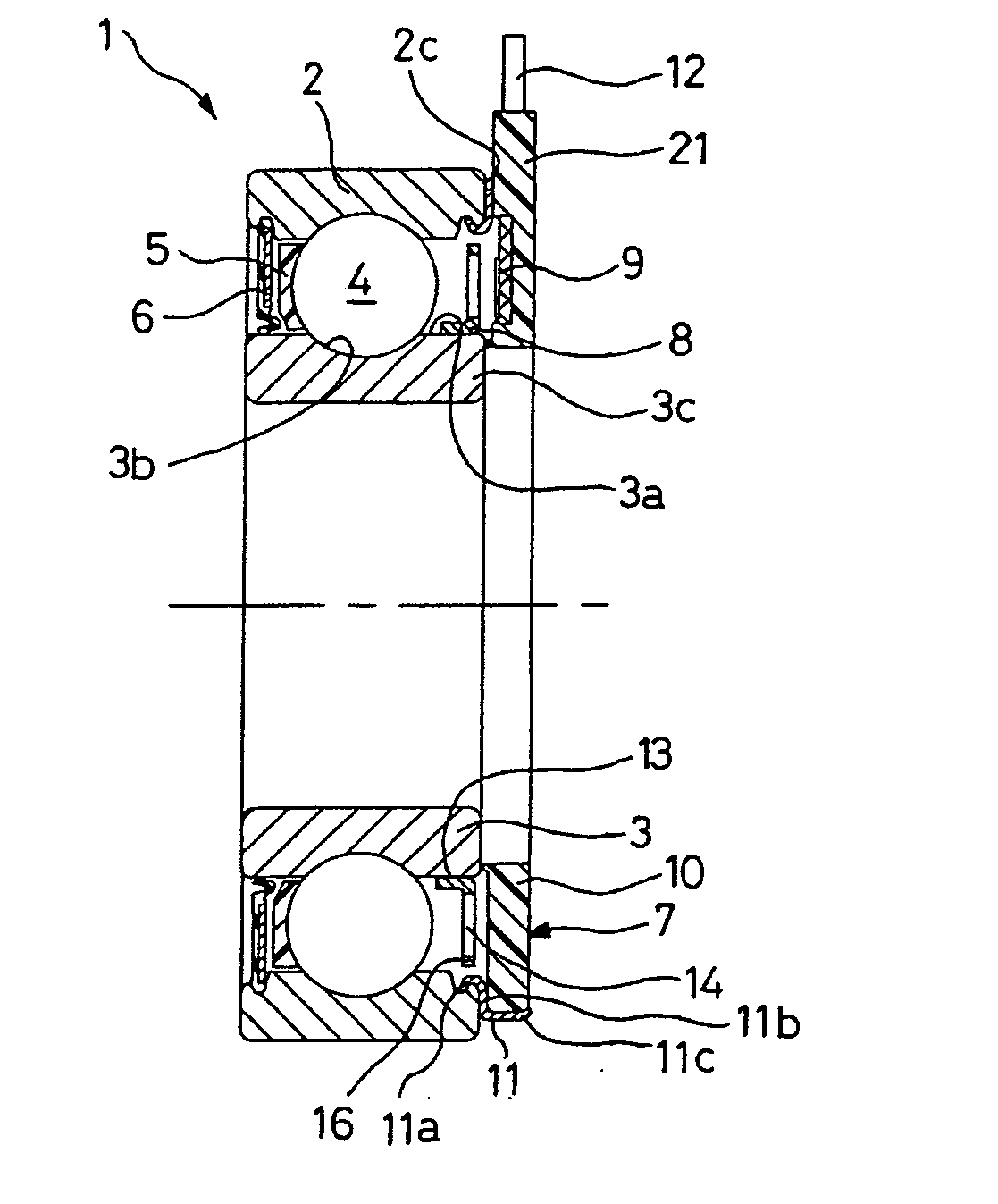
[0026] As illustrated in FIG. 1, the rolling bearing 1 may include an outer track 2; an inner track 3; a row of rolling elements 4, such as balls, placed between the outer track 2 and the inner track 3 and retained by a cage 5; a seal 6 on one of its sides; on the opposite side a speed sensor 5 integrated with the outer track 2; and an encoder 8 integrated with the inner track 3. In an embodiment, the outer track may be nonrotating and the inner track may be rotating. In an embodiment, the outer track may be rotating and the inner track may be rotating.

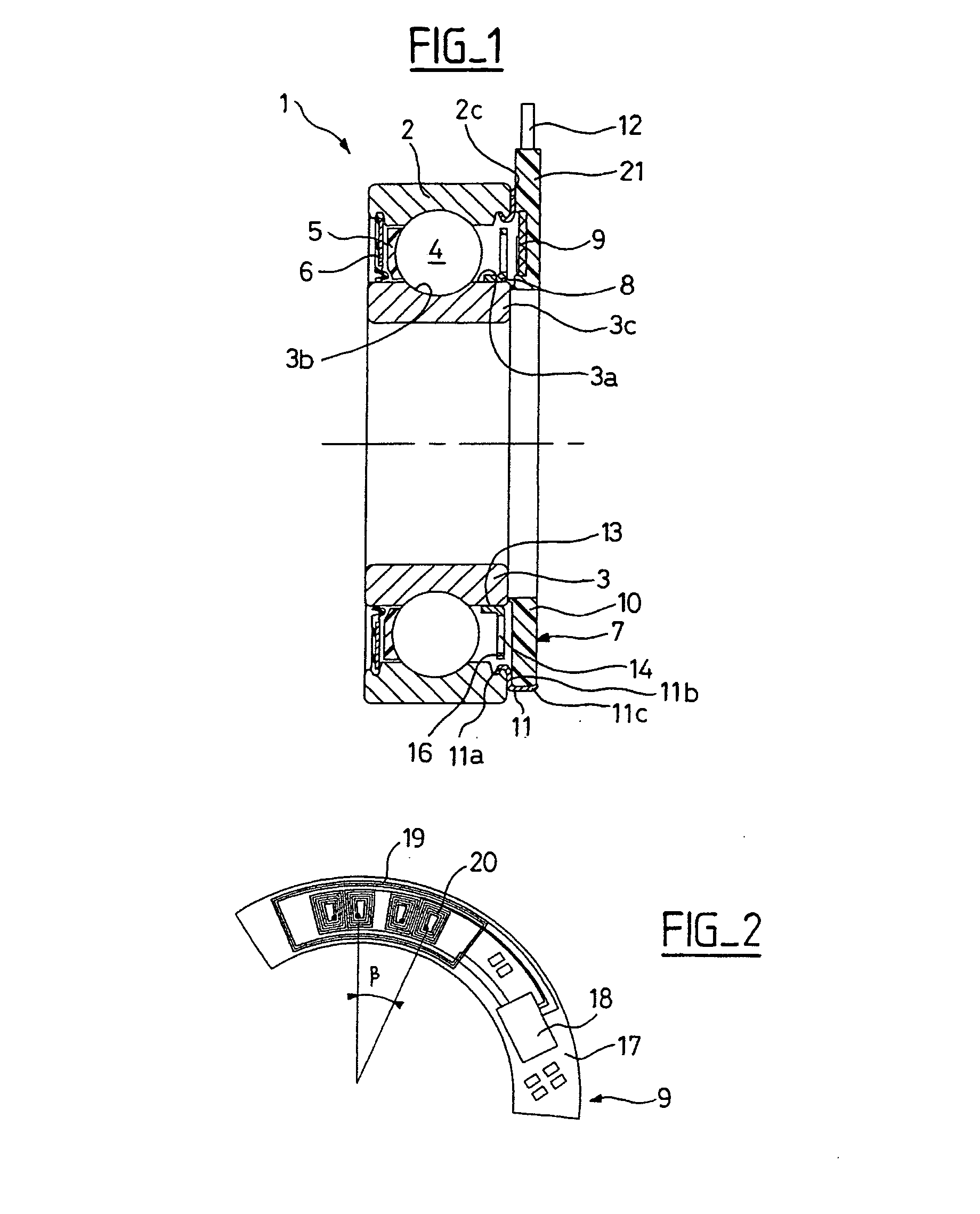
[0027] In some embodiments, a sensor 7 may include a detection portion 9 as depicted in greater detail in FIG. 2. A sensor may include a support unit 10 made of a synthetic material and a metal element 11 fitted onto a bearing surface of the outer track 2. A groove in a track may be used to attach the seal provided in noninstrumented antifriction bearings. A cable 12 may be coupled to the detection portion 9 and may be used to transm...


PUM


Abstract

An instrumented ball-bearing may include a rotating part, a non-rotating part, and an assembly for detecting rotation parameters. The assembly for detecting rotation parameters may include an encoder and a sensor. The sensor may be integrated with the non-rotating part. The sensor may include a sensor unit and at least a microcoil. The microcoil may have a substantially planar winding. The microcoil may be positioned in the sensor unit of the non-rotating part such that the microcoil may be positioned axially opposite the encoder.

Description

BACKGROUND OF THE INVENTION [0001] 1. Field of the Invention [0002] The present invention generally relates to an antifriction bearing in which a rotating member of the bearing supports an encoder and a nonrotating member of the bearing supports a sensor that may be used to determine rotation parameters such as the speed or the angular position of the rotating element supporting the encoder. The present invention also relates to antifriction bearings for use in electric motors, which are required to operate in severe speed and temperature conditions. [0003] 2. Description of the Relevant Art [0004] French Patent No. 2,754,903, describes an antifriction bearing that includes a sensor on the nonrotating track, of the Hall effect probe type, and an encoder on the rotating track moving in rotation with a slight air gap relative to the sensor while being capable of producing in the sensor a periodic signal with a frequency proportional to the rotation speed of rotation of the rotating tr...

Claims


Application Information

Patent Timeline
Patent Type & Authority Applications(United States)
IPC IPC(8): F16C41/04F16C19/52F16C41/00G01D5/245G01P3/44G01P3/488H02K11/00
CPCG01P3/443G01P3/488F16C41/007F16C19/06F16C2380/26
Inventor GALLION, SAMUELLAUFERON, FRANCK
Owner AB SKF
Why Eureka
Try Eureka