
Camera shaking correcting method, camera shaking correcting device, and image pickup device

a technology of camera shake and correcting method, which is applied in the field of camera shake correcting method, camera shake correcting device, and image pickup device, can solve the problems of high computational capacity, long computing time, and poor quality of photographed images, and achieve simple computation processing and suppress the occurrence of blurring

Active Publication Date: 2006-05-18
FUJIFILM HLDG CORP +1
View PDF1 Cites 48 Cited by
  • Summary
  • Abstract
  • Description
  • Claims
  • Application Information

AI Technical Summary

Benefits of technology

[0023] The present invention was developed in view of the aforementioned, and provides a camera shaking correcting method, a camera shaking correcting device, and an image pickup device which can suppress the occurrence of blurring in a photographed image by simple computation processing.
[0024] Further, the present invention provides a camera shaking correcting device and an image pickup device in which a substantially uniform characteristic can be obtained regardless of the frequency, and which aim for reliable reduction in drift, and which enable highly-accurate shaking correction.

Problems solved by technology

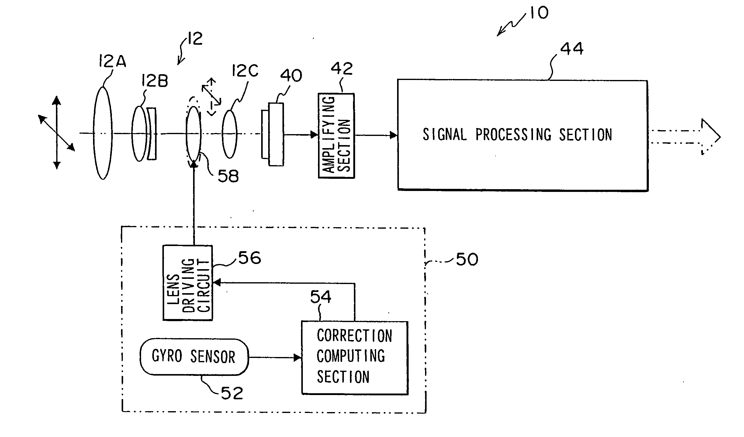
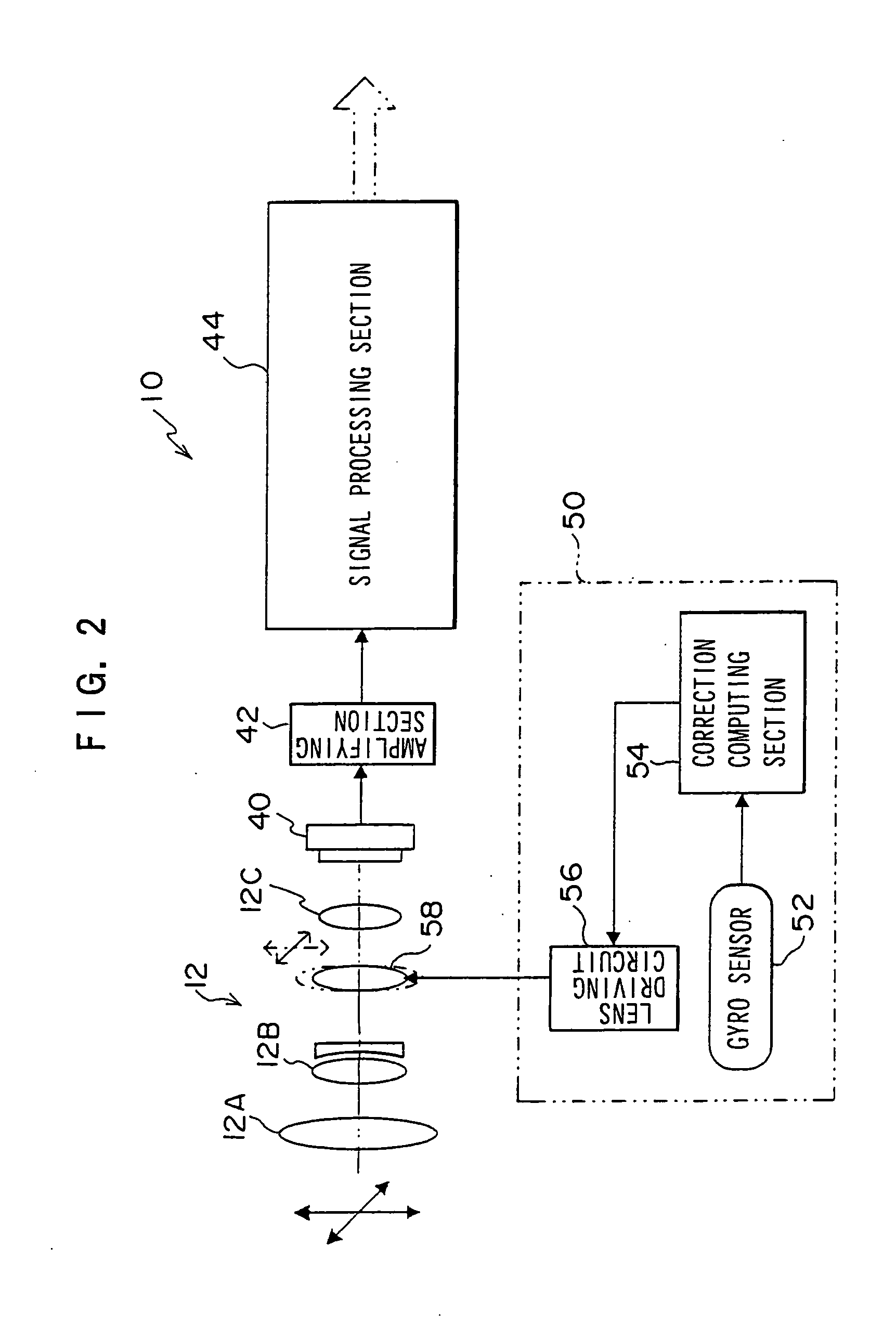
Because optical-type blurring correction compensates changes in the image angle of the device main body by optical axis rotation, if there is a time delay (time lag) from the detection of the shaking of the main body to the lens control, shaking amount corresponding to that delay time will appear as blurring of the image which is imaged at the image pickup element, and the quality of the photographed image will deteriorate.
To this end, complicated computation processing utilizing a large amount of data is necessary, and a system having a high computational capacity must be used or a long computing time is required.
This therefore leads to an increase in the size of and an increase in the cost of the pickup device, and substantial elimination of blurring is difficult.
Therefore, the detection sensitivity is low.
Thus, it is easy for fluctuations in output to arise due to affects such as noise or drift of the DC or the like due to the temperature characteristic or the like, and as a result, it is easy for the shaking correcting device to function erroneously.
Therefore, if the DC component removal by the HPF 206 is made to be great, the low frequency camera shaking components are damped, and a sufficient camera shaking correcting effect cannot be obtained.
Namely, it is difficult to simultaneously achieve both drift reduction and precise shaking detection of low frequencies at the output circuit of the angular velocity sensor.
However, drift following which uses such a cyclic filter has a high band pass limiting (LPF) characteristic with respect to the input signal.
In this way, the level of the correction value obtained by integrating the detection value differs in accordance with the frequency, and the problem arises that an optimal correction level can be obtained only with respect to vibrations of specific frequencies.

Method used


Image

  • Camera shaking correcting method, camera shaking correcting device, and image pickup device
  • Camera shaking correcting method, camera shaking correcting device, and image pickup device
  • Camera shaking correcting method, camera shaking correcting device, and image pickup device

Examples


first embodiment

[0091] As shown in FIG. 3, the gyro sensor 52 has a vertical angular velocity sensor 52A and a horizontal angular velocity sensor 52B. The vertical angular velocity sensor 52A and the horizontal angular velocity sensor 52B detect the angular velocity in the vertical direction and the angular velocity in the horizontal direction of the digital camera 10, and output signals corresponding to the detected angular velocities. Note that, instead of the angular velocity sensors, acceleration sensors or angular acceleration sensors or the like may be used.

[0092] The outputs of the gyro sensor 52 are inputted to the correction computing section 54 via an amplifying circuit (Amp) 60 and an A / D converter 62. The correction computing section 54 has a microcomputer (not shown), and an integration computing section 64 (integration processing section) and a correction amount computing section 66 are formed thereby.

[0093] Due to the lens driving circuit 56 driving an actuator (not illustrated) on...

second embodiment

[0127] The schematic structure of main portions of the shaking correcting module 50 relating to a second embodiment are shown in FIG. 7. The gyro sensor 52 has the vertical angular velocity sensor 52A and the horizontal angular velocity sensor 52B. The vertical angular velocity sensor 52A and the horizontal angular velocity sensor 52B detect the angular velocity in the vertical direction and the angular velocity in the horizontal direction of the digital camera 10, and output signals corresponding to the detected angular velocities. Note that, instead of an angular velocity sensor, an acceleration sensor, an angular acceleration sensor, or the like may be used.

[0128] HPFs 60, which damp low-band frequency components from the signals outputted from the vertical angular velocity sensor 52A and the horizontal angular velocity sensor 52B respectively, and amplifier circuits (Amp) 62, which amplify the signals which have passed through the HPFs 60, are provided at the gyro sensor 52. In...

third embodiment

[0174] A third embodiment of the present invention will be described next. Note that the basic structure of the third embodiment is the same as the above-described second embodiment. In the third embodiment, parts which are the same as in the second embodiment are denoted by the same reference numerals, and description thereof is omitted.

[0175] The schematic structure of a shaking correcting module 50A applied to the third embodiment is shown in FIG. 15.

[0176] In addition to the A / D converter 64, the integration processing section 66, and the control voltage converting section 68 at a correction computing section 54A, the shaking correcting module 50A also has a filter processing section 86 between the integration computing section 66 and the control voltage converting section 68.

[0177] At the filter processing section 86, the drift component contained in the angular velocity signal is removed from the integrated value which is obtained by integrating the angular velocity signal ...


PUM


Abstract

Output of a gyro sensor is read at intervals of control time ts, time integration is carried out, an integrated value is computed, and an amount of change in an integrated value is determined from a difference between the calculated integrated value and an integrated value of a previous time. Thereafter, on the basis of the amount of change and a delay time determined by a shaking correcting module and the control time, an addition value (an acceleration value of an integrated value of the current time) is computed in order to obtain an amount of movement of a shift lens which can compensate tilting of an optical axis of a lens. After the computed addition value is added to the integrated value of the current time, a control value for moving the shift lens is computed by using the integrated value after addition.

Description

CROSS-REFERENCE TO RELATED APPLICATION [0001] This application claims priority under 35 USC 119 from Japanese Patent Application Nos. 2004-329004 and 2004-341504, the disclosures of which are incorporated by reference herein. BACKGROUND OF THE INVENTION [0002] 1. Field of the Invention [0003] The present invention relates to an image pickup device such as a digital still camera, a digital video camera, or the like which obtains image data corresponding to a photographed image, and in particular, relates to a camera shaking correcting method of an image pickup device equipped with an optical-type camera shaking correcting function, and to a camera shaking correcting device and an image pickup device. [0004] 2. Description of the Related Art [0005] Of course among digital video cameras, digital still cameras, and the like, and among silver salt photographic cameras and the like as well, there are cameras equipped with a camera shaking correcting function which corrects blurring of a p...

Claims


Application Information

Patent Timeline
IPC IPC(8): G03B17/00
CPCG02B27/646G03B17/02H04N5/23248H04N5/23254H04N5/23258H04N23/6811H04N23/68H04N23/6812
Inventor EBATO, TAKASHI
Owner FUJIFILM HLDG CORP
Learn More