
Grain tank unloader and clean out control

a technology for unloading and cleaning out, applied in the direction of transportation items, loading/unloading vehicle arrangment, refuse collection, etc., can solve the problems of grain cracking, grain damage, grain auger damage, etc., and achieve the effect of reducing the load and stress on the grain tank, reducing the load and stress, and reducing the load

Active Publication Date: 2006-05-18
BLUE LEAF I P INC
View PDF16 Cites 24 Cited by
  • Summary
  • Abstract
  • Description
  • Claims
  • Application Information

AI Technical Summary

Benefits of technology

The invention is a control system for an agricultural combine that prevents problems such as grinding and cracking of grain during the unloading process. The control system automatically initiates the operation of the unloader conveyor to create space for the grain, and then the grain tank conveyor moves the grain into the inlet of the unloader conveyor. The control system also includes an anti-stall feature that discontinues the operation of the grain tank conveyor to prevent damage to the conveyor and grain in case of problems. Overall, the control system improves the efficiency and safety of the unloading process.

Problems solved by technology

As a result, a problem that can occur if the grain tank and unloader augers are started simultaneously, or the grain tank auger is started first, is that the grain tank auger can force or pack the grain into and against the grain in the lower unloader housing, thereby causing grinding, cracking of and other damage to the grain.
As another problem or shortcoming, if the unloader conveyor is loaded with grain when pivoted between the sidewardly extending unloading position and the stored position, greater loads and stress are placed thereon and on the supporting structure thereof compared to if the unloader is empty.
As still another possible problem, if the unloader auger should stall, for instance, due to a mechanical problem with the unloader drive, formation or induction of a slug of grain in the unloader tube, and the grain tank auger continues to operate, the inlet of the unloader can be packed with grain, which can result in excessive grain damage and / or damage to the grain tank auger.

Method used


Image

  • Grain tank unloader and clean out control
  • Grain tank unloader and clean out control
  • Grain tank unloader and clean out control

Examples


Embodiment Construction

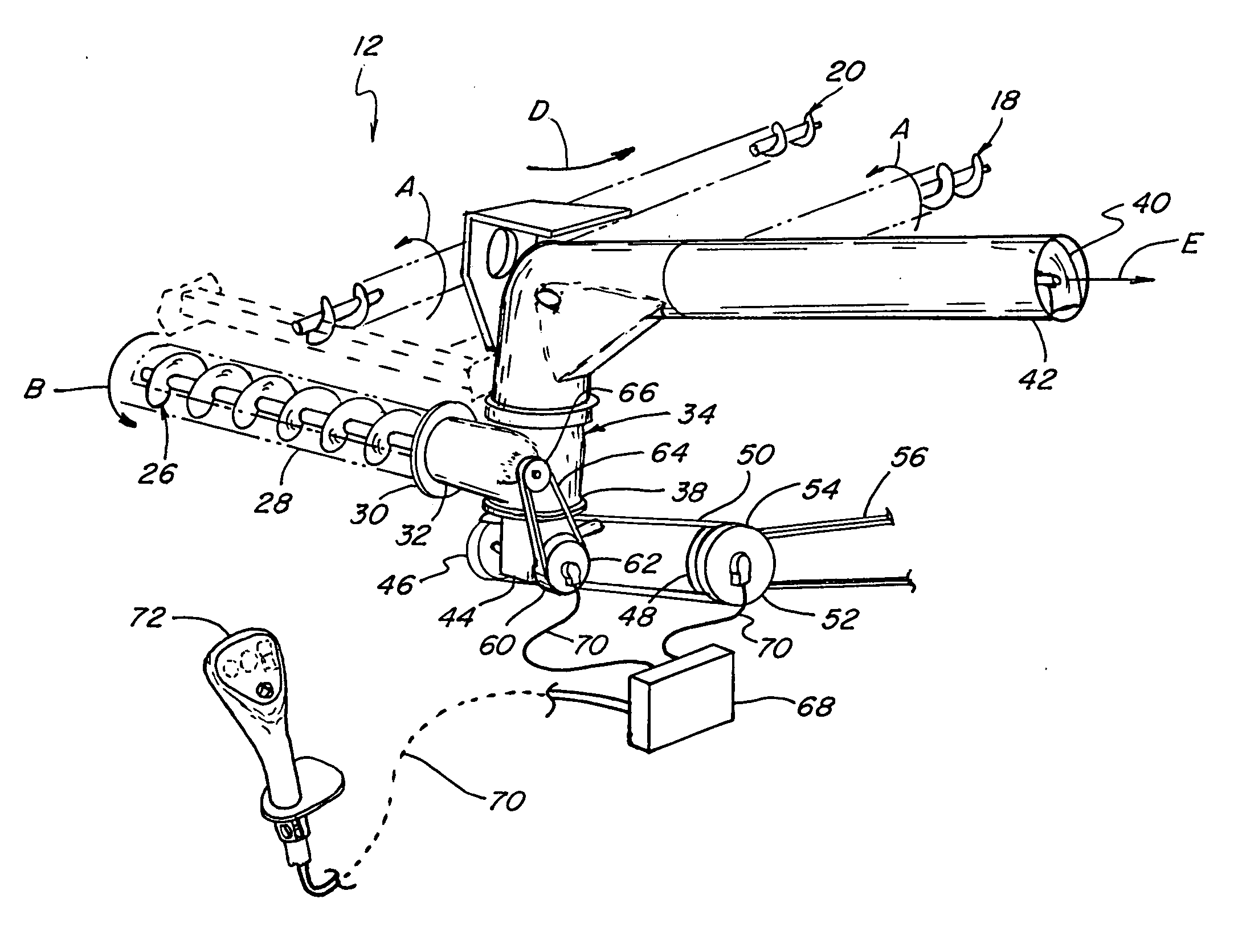
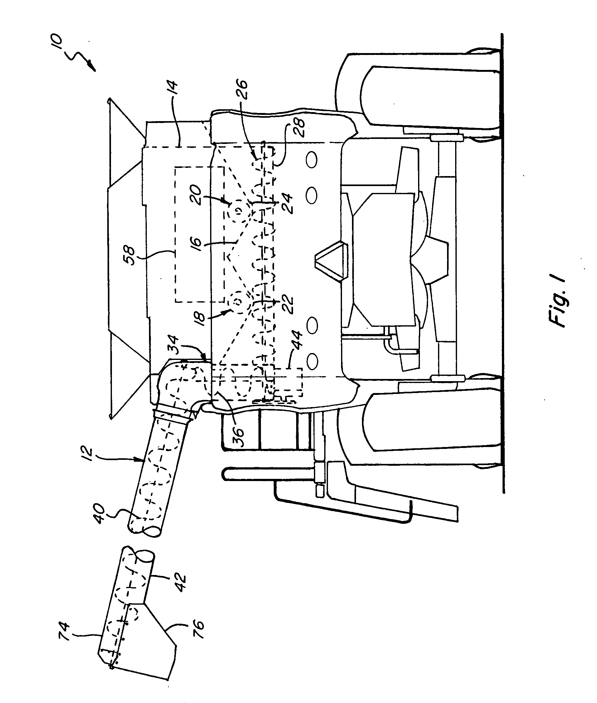
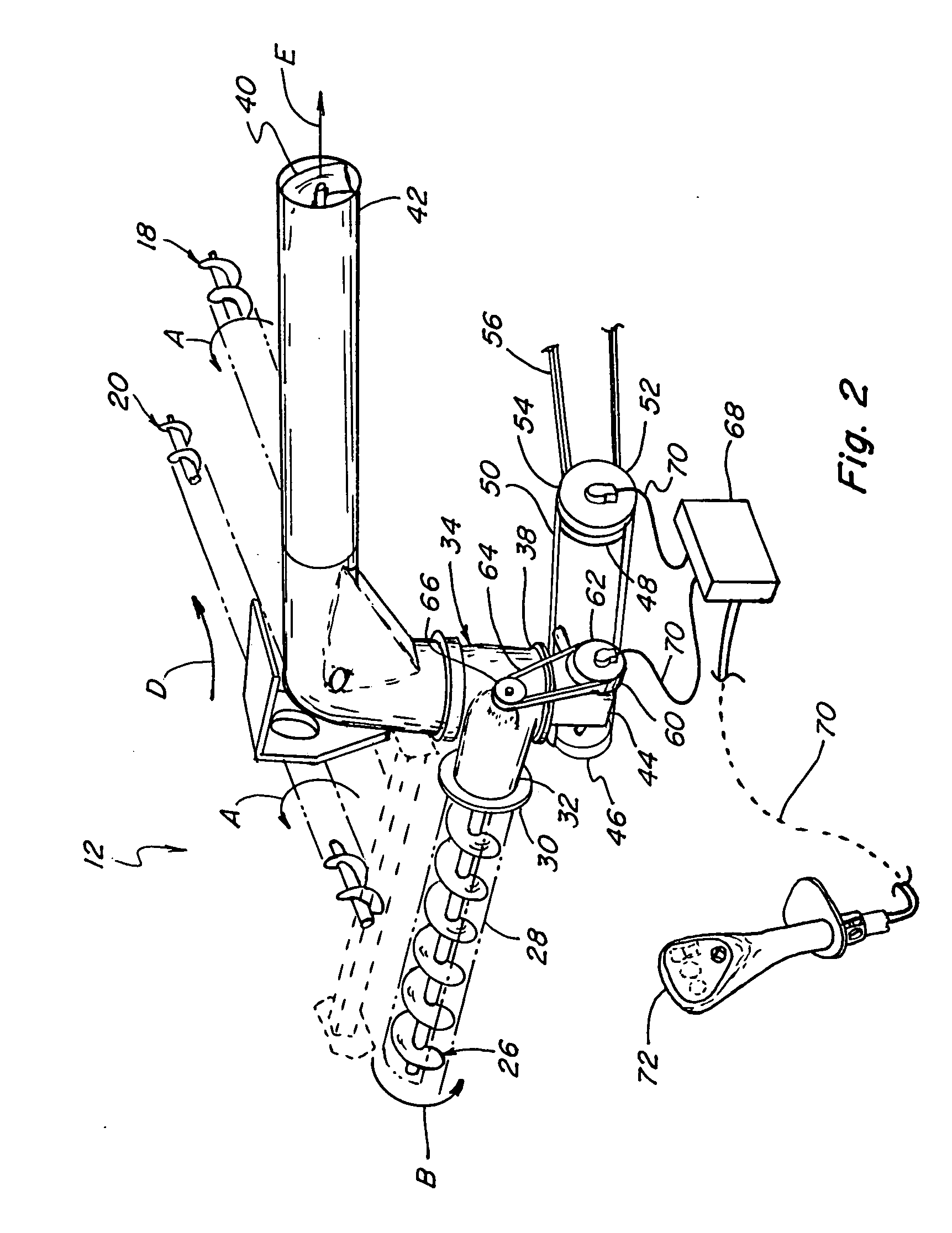
[0015] Referring now the drawings, in FIG. 1, a representative agricultural harvesting machine 10 is shown, including an unloader 12 operable for unloading grain from a grain tank located on an upper region of harvesting machine 10. Here, harvesting machine 10 is depicted as a well known, commercially available combine operable for harvesting a wide variety of grains, including, but not limited to, wheat, beans, corn, rice, and the like. Typically, the grain is harvested and threshed from stalks, pods, or other crop material, and conveyed away from a cleaning system of machine 10 by a clean grain conveyor to a grain elevator (not shown). The grain elevator then lifts the grain upwardly to a grain delivery conveyor which is operable for discharging the grain into grain tank 14 onto a floor 16 thereof. When grain tank 14 is filled with grain, or filled to a desired level, unloader 12 can be operated for unloading the grain from tank 14, onto the ground, or into a wagon, truck or other...


PUM


Abstract

An unloader control for an unloader conveyor and grain tank conveyor of an agricultural combine, which, when an unload command is received, will automatically initiate operation of the unloader conveyor to commence conveying grain in an inlet end thereof toward the outlet end thereof so as to allow smooth transition of grain from the grain tank conveyer to the inlet end of the unloader conveyor, then automatically initiate operation of the grain tank conveyor for moving grain into the inlet end of the unloader conveyor, and, when a clean out command is received during operation of the unloader conveyor and the grain tank conveyor, will automatically cease operation of the grain tank conveyor, then, after a sufficient time period for the unloader conveyor to convey substantially all of any grain therein through the outlet end, automatically cease operation of the unloader conveyor.

Description

TECHNICAL FIELD [0001] This invention relates generally to an unloader control for a grain tank of an agricultural combine, and more particularly, to a control for grain tank unloading and clean out which provides an operating routine for reducing start up torque loading and grain damage at commencement of grain unloading, a routine for cleaning out the unloader conveyor after unloading, and which can provide protection for a grain tank conveyor drive under severe loading conditions. BACKGROUND [0002] Grain tanks of combines commonly have an associated unloader conveyor operable for conveying grain from the grain tank to another location such as to a grain truck or wagon. An unloader conveyor typically includes an elongate, enclosed tubular housing containing a helical auger and is oriented horizontally or at a small acute angle to horizontal. The unloader conveyor is typically pivotally supported in cantilever relation by a lower end of an upstanding or vertical lower unloader conv...

Claims


Application Information

Patent Timeline
Patent Type & Authority Applications(United States)
IPC IPC(8): B60P1/00
CPCA01D41/1217A01K5/002B60P1/42
Inventor TALBI, AZIZFREGO, JEFFREY D.CREGO, JOHN B.
Owner BLUE LEAF I P INC
Learn More