Assay devices

a technology of assay and insert, which is applied in the field of assay devices, can solve the problems of affecting the sensitivity of paper strip tests, death and illness, and take several days to obtain, and achieve the effects of reducing the stress of the insert, less capillary force, and reducing the amount of air bubbles in the spa

Inactive Publication Date: 2006-05-18
UMEDIK
View PDF6 Cites 17 Cited by
  • Summary
  • Abstract
  • Description
  • Claims
  • Application Information

AI Technical Summary

Benefits of technology

[0018] The insert is preferably press-fit into the cavity. Protrusions are preferably provided on either the edge of the insert or the interior surface of the sidewall of the cavity, or both, to provide the press-fit, thereby reducing stress on the insert. The insert and the side wall of the cavity preferably have portions or vents which are spaced a greater distance from each other than the distance between the second surface of the insert and the major surface of the cavity, so that less capillary force is generated between the insert and the sidewall, than in the space. Air may escape from the space through the vents. In addition, the fluid sample evenly fills the space, instead of rapidly moving along the edge of the insert. Air bubbles in the space are thereby minimized.
[0019] A lid is preferably provided, slideably engaging the base. The lid may be selectively moved over the input portion after a fluid sample is applied, to protect the fluid sample from contamination. In addition, the lid maintains humidity in the region around the fluid sample, slowing evaporation of the fluid sample.
[0020] A wall is preferably provided around the input portion to also protect the fluid sample and to prevent the fluid sample from being applied to or to moving onto the reading portion.

Problems solved by technology

Contaminated poultry and meat products are a major cause of these deaths and illness.
It could take several days to obtain results.
However, paper strip tests have low sensitivity.
Contamination of water supplies also causes illness and death.
Both types of tests are costly and time consuming and require significant handling.
They are not; therefore, suitable for field-testing.
Standard medical tests for quantifying markers, such as ELISA-type assays, are time consuming and require relatively large volumes of fluid.
Use of such fibrous materials may reduce the rate and volume of fluid flow through the assay device, increasing the time required to obtain the test results.
When health concerns require that test results be obtained as soon as possible, such delays are not acceptable.
Centrifugation, however, requires cumbersome equipment, making it inappropriate for field-testing.
Relatively large volumes of fluid are also typically required.
There is no convenient location for placement of the sample on the disclosed device.
The disclosed devices appear to be complex to manufacture and use.

Method used


Image

  • Assay devices
  • Assay devices
  • Assay devices

Examples


Embodiment Construction

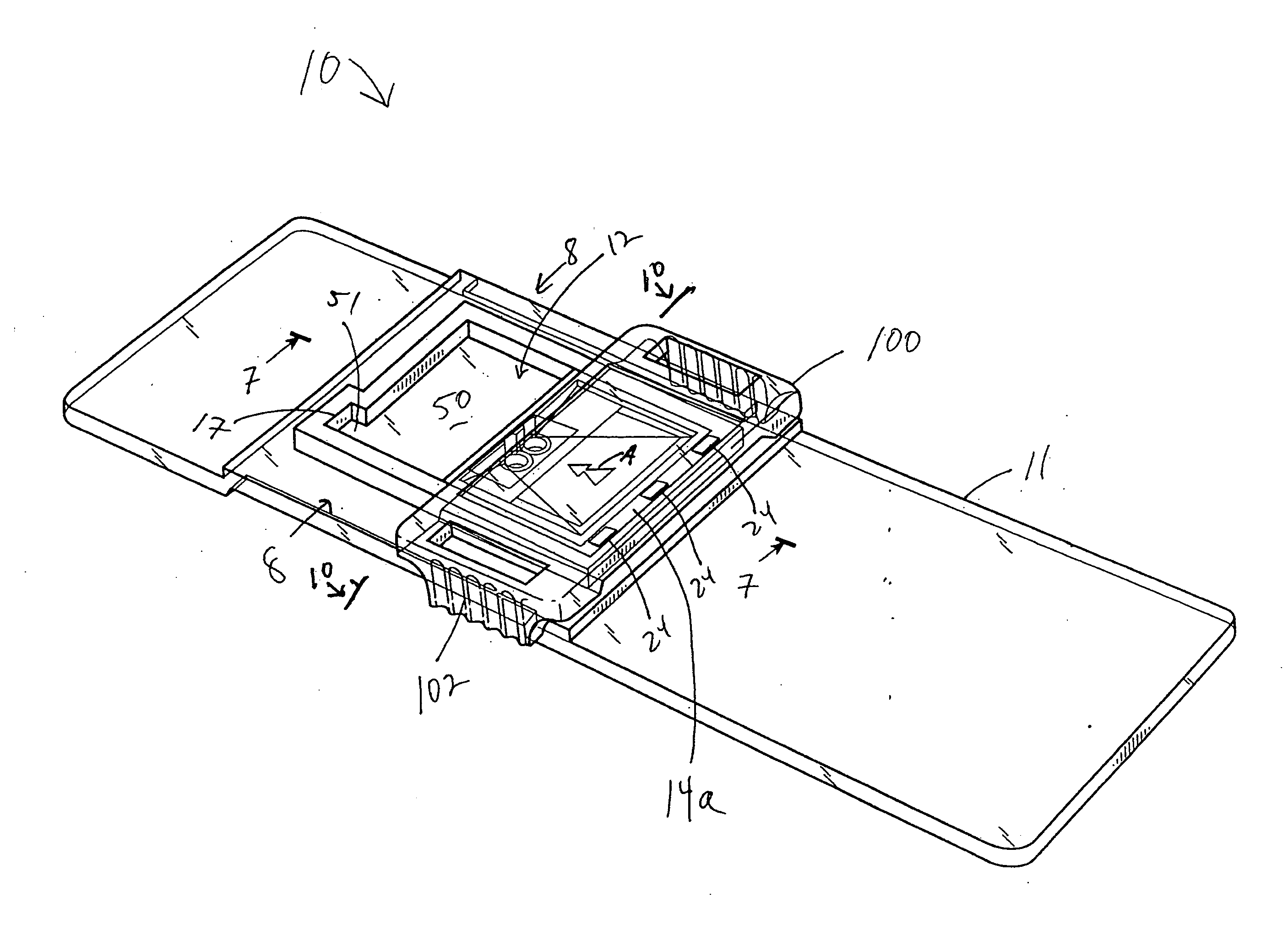
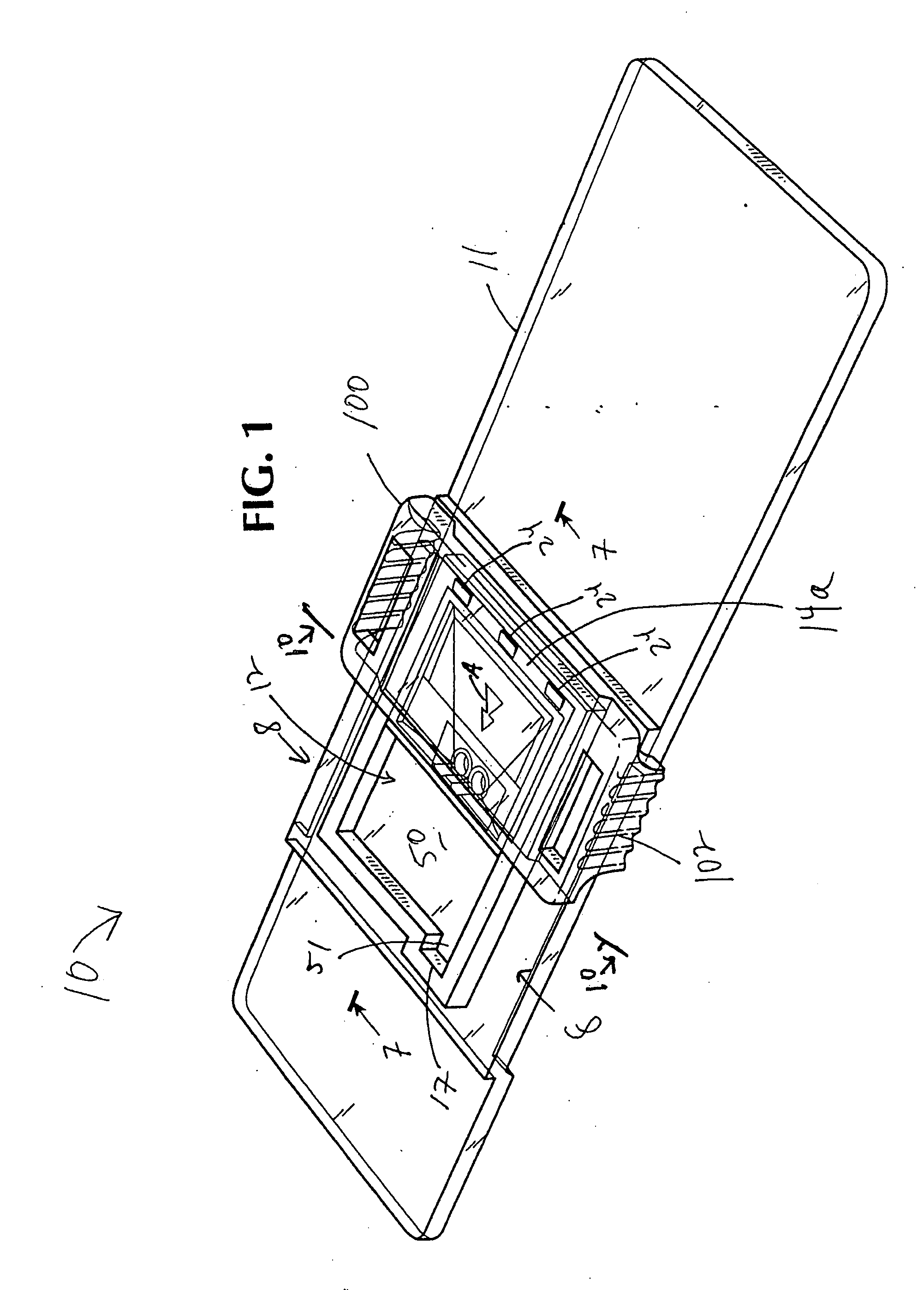
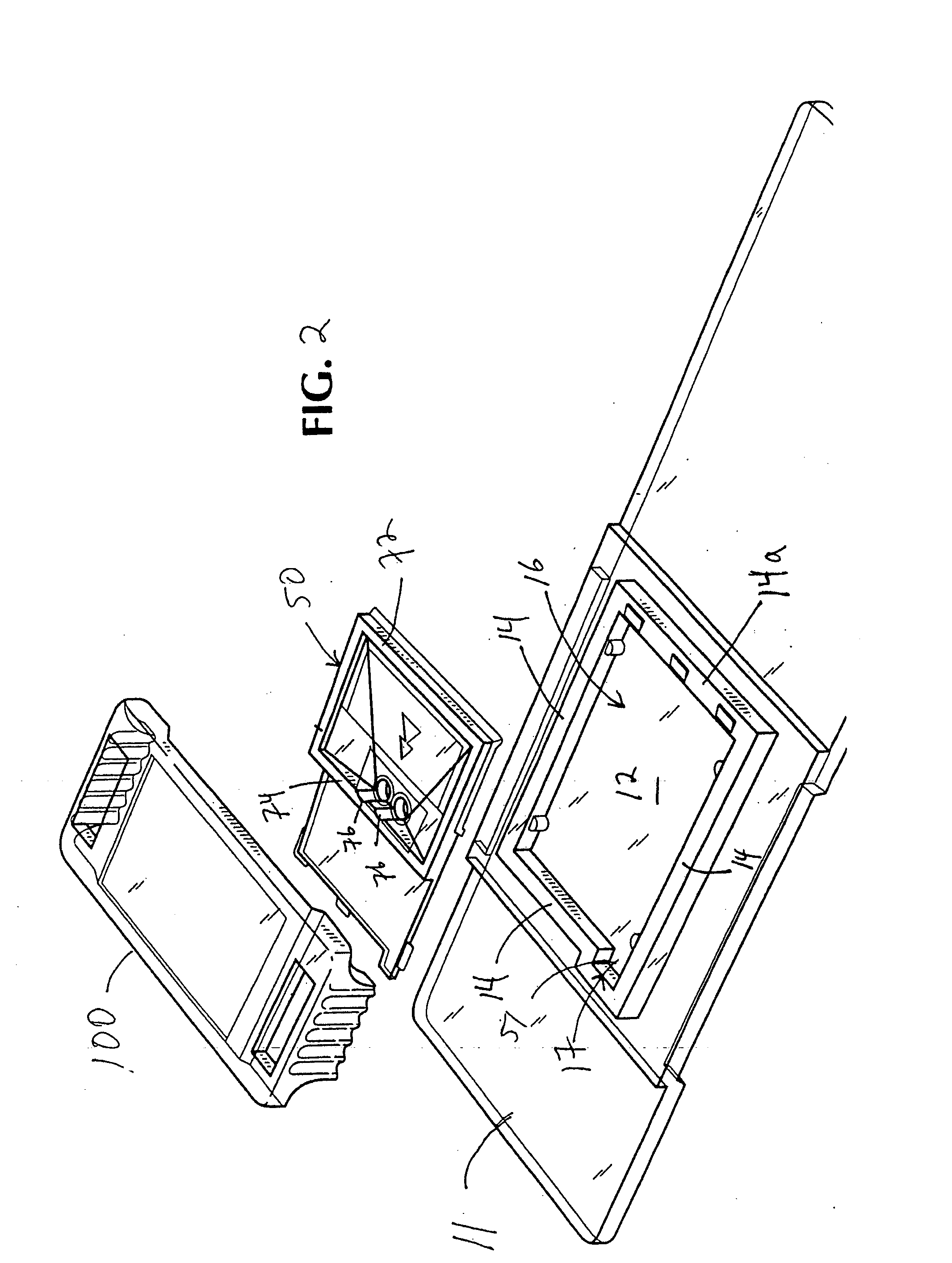
[0042]FIG. 1 is a perspective view of the assay device 10 in accordance with one embodiment of the present invention. The assay device 10 comprises three pieces: a base 11, an insert 50 within a cavity 12 defined by the base and a lid 100 snapped over the base. FIG. 2 is an exploded view of the assay device 10 of FIG. 1, more clearly showing the base 11, the cavity 12, the insert 50 and the lid 100. FIG. 3 is a top view of the assay device 10. Preferably, the base 11, the insert 50 and the lid 100 are molded in plastic. Preferred materials are discussed below.

[0043]FIG. 4 is a top view of the base 11. As shown in FIGS. 1-4, the base 11 defines a cavity 12 with a sidewall 14 surrounding a major bottom wall 16. The cavity 12 has an open face opposite the major bottom wall 16. In this embodiment, the sidewall 14 comprises four walls connected to form a rectangle. The sidewall 14 may also define a circle, an oval, or any other convenient shape. The shape of the insert 50 preferably mat...


PUM

PropertyMeasurementUnit
angleaaaaaaaaaa
distanceaaaaaaaaaa
distanceaaaaaaaaaa

Abstract

Assay devices are disclosed comprising a base defining a cavity and an insert received in the cavity. The cavity has major surface and at least one sidewall, preferably surrounding the major surface. The insert comprises a first surface with a portion opposing the major surface of the cavity. A space is provided between the portion of the first surface and the major surface for the receipt of a fluid sample. The space has an entrance defined by the first surface of the insert and the major surface. The insert also comprises a second surface opposing the first surface and having an input portion for the application of a fluid sample. The input portion is in fluid communication with the entrance to the space, such that a fluid sample applied to the input portion passes to the entrance to the space and into the space. At least one or more passages is preferably defined through the insert, for passage of the fluid sample through the insert, to the entrance to the space. The second surface of the insert also comprises a reading portion for analyzing the fluid sample in the space. Reagents may be provided in the space for identifying and quantifying the presence of one or more analytes in the fluid sample. Preferably, the assay device is transparent. The portion of the first surface and the first surface of the insert and the major surface of the cavity may be separated by a distance effective to cause capillary flow of the fluid sample into the space from the entrance to the space.

Description

RELATED APPLICATIONS [0001] The present application is a continuation in part of PCT / US00 / 13056, filed on May 12, 2000, which is a continuation-in-part of U.S. Ser. No. ______ (to be assigned) (Attorney Docket Number 254 / 112), filed on May 16, 2001, which is a national phase applications based on PCT / CA99 / 01079, filed on Nov. 12, 1999, which are both continuation in parts of U.S. Ser. No. 09 / 335,732, which was filed on Jun. 18, 1999. These application are assigned to the assignee of the present invention and are incorporated by reference herein, in their entireties.FIELD OF THE INVENTION [0002] The present invention is an assay device for identifying the presence or absence of an analyte in a fluid sample. A quantitative measurement of the concentration or amount of the analyte in the fluid sample may also be obtained. The assay device may include a filter for separating unwanted components of the fluid sample greater than a predetermined size from the fluid components of the sample...

Claims


Application Information

Patent Timeline
Patent Type & Authority Applications(United States)
IPC IPC(8): G01N33/558B01L3/00G01N1/28G01N33/49G01N33/50G01N33/543
CPCB01L3/5027B01L3/502715B01L3/502753B01L9/527B01L2200/025B01L2200/027B01L2300/045B01L2300/0609B01L2300/0654B01L2300/0681B01L2300/0825B01L2300/168B01L2400/0406G01N1/4077G01N21/05G01N33/491G01N33/5002G01N33/54366G01N2021/0346
Inventor LEA, PETERGAL, MICHELLESZABADOS HAYNES, NICOLEPROKOPOWICZ, RICHARD A.
Owner UMEDIK
Why Eureka
Try Eureka