Light gas component separation from a carbon dioxide mixture

a technology of light gas and carbon dioxide mixture, which is applied in the direction of lighting and heating apparatus, refrigeration machines, solidification, etc., can solve the problems that the low temperature process illustrated in these patents is ineffective for high carbon dioxide in the feed

Active Publication Date: 2006-05-25
PRAXAIR TECH INC
View PDF12 Cites 34 Cited by
  • Summary
  • Abstract
  • Description
  • Claims
  • Application Information

AI Technical Summary

Benefits of technology

[0014] In accordance with another aspect of the present invention, at least one light component can be separated from a supercritical pressure carbon dioxide containing gaseous mixture containing at least about 30 mole percent carbon dioxide. In accordance with this aspect of the present invention, a pressurized feed stream composed of the gaseous carbon dioxide containing mixture can be cooled and expanded so at least a portion of the carbon dioxide liquefies. The pressurized feed stream can be degassed to produce a vapor stream enriched in the at least one light component and a liquid stream enriched in carbon dioxide. The liquid stream can be vaporized to obtain a vaporized liquid stream. Either the vaporized liquid stream can be compressed or the liquid stream can be pumped so that the vaporized liquid stream is obtained at an elevated pressure. This repressurization can be above the critical pressure of the liquid. In such manner, the light components can be removed from the incoming stream and the carbon dioxide can be returned to a source, for instance, a pipeline at pressure in an energy efficient manner.

Problems solved by technology

The low temperature processes illustrated in these patents would be ineffective for high levels of carbon dioxide in the feed due to the fact that the carbon dioxide would solidify.

Method used


Image

  • Light gas component separation from a carbon dioxide mixture
  • Light gas component separation from a carbon dioxide mixture
  • Light gas component separation from a carbon dioxide mixture

Examples


Embodiment Construction

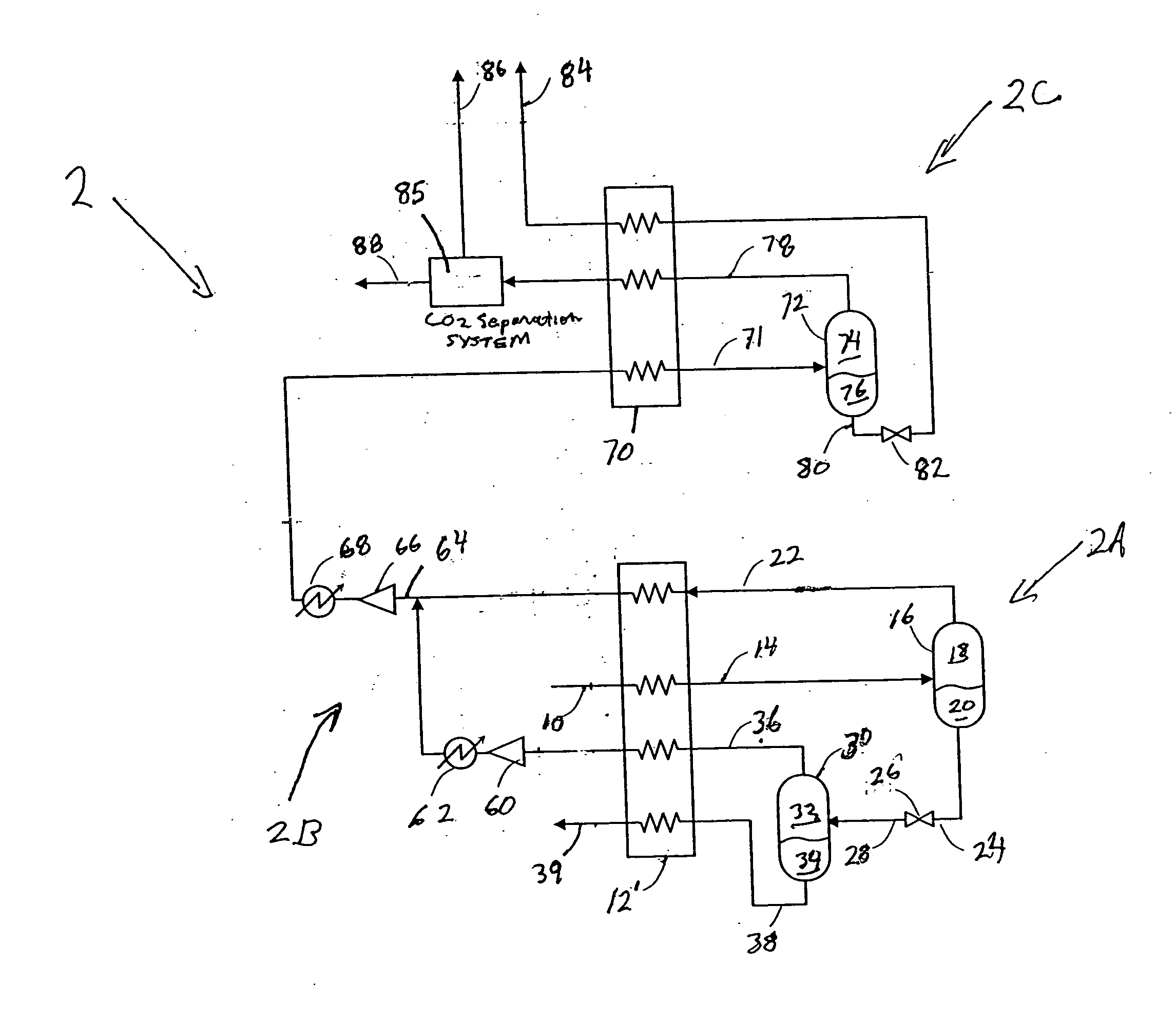
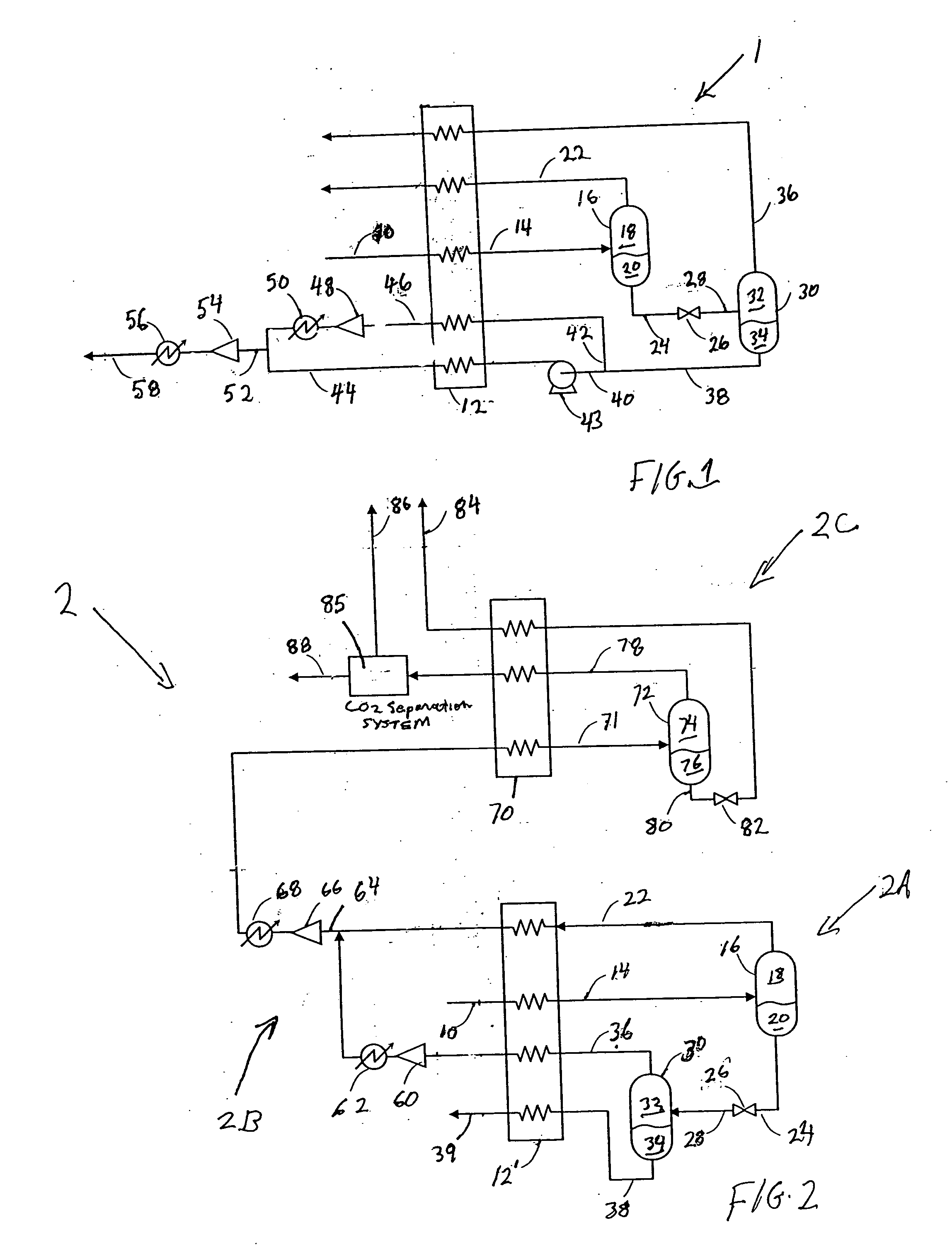
[0023] With reference to FIG. 1 a process flow diagram of an apparatus 1 for carrying out a method in accordance with the present invention is illustrated that is designed to treat subcritical feed streams.

[0024] A pressurized feed stream 10 that is composed of a carbon dioxide containing gaseous mixture is obtained at a pressure in a range from between about 200 psia to about 850 psia. More preferably, the pressure of pressurized feed stream 10 is in a pressure range of between about 350 psia and about 750 psia. The pressurized feed stream 10 contains less than 10 mole percent helium and at least 50 mole percent carbon dioxide. Streams containing about 0.1 to 3.0 mole percent helium or greater may be treated. The source of pressurized feed stream 10 may be a natural well or a well head gas obtained at an oil well in which carbon dioxide has been used to enhance recovery. Alternatively, the source gas may be such well gas which has been previously compressed and / or purified and dri...


PUM


Abstract

A method of separating one or more light components, such as helium, from a carbon dioxide containing stream. A two-phase stream is obtained, at least in part, by cooling a pressurized feed stream to at least partially condense such stream. The stream that is subsequently degassed to produce a first vapor stream enriched in the light component(s) and a first liquid stream containing an entrained fraction of the light component(s). The first liquid stream is expanded to create another two-phase stream that is degasified to produce a second vapor stream that is also enriched in the light component(s) and a second liquid stream having an enriched carbon dioxide content. The second liquid stream is repressurized and vaporized. In case of a supercritical feed, the pressurized feed stream is expanded after having been cooled. Thereafter, the feed is degassed to produce the light component enriched vapor stream and a liquid stream enriched in the carbon dioxide. The resultant vapor streams, enriched in the light component(s) may then be further processed to isolate the light components.

Description

FIELD OF THE INVENTION [0001] The present invention relates to a method of separating one or more light gas components in a carbon dioxide containing gaseous mixture containing a high concentration of carbon dioxide. More particularly, the present invention relates to such a method in which the carbon dioxide containing mixture is degassed to produce vapor and liquid streams and the liquid stream is expanded and further degassed to produce additional vapor and liquid. BACKGROUND OF THE INVENTION [0002] Helium occurs naturally in very low concentrations within underground natural gas and carbon dioxide reservoirs. In some instances, helium is present at sufficiently high concentrations to justify its recovery. In general, helium can be effectively recovered from gas streams containing at least 0.1 mole percent helium or greater. Helium is typically first concentrated into a crude helium stream that contains about 70 mole percent helium. The crude helium can be stored, typically in un...

Claims


Application Information

Patent Timeline
Patent Type & Authority Applications(United States)
IPC IPC(8): F25J3/00
CPCF25J3/0209F25J3/0219F25J3/0252F25J3/0266F25J3/029F25J3/061F25J3/062F25J3/0655F25J3/067F25J3/069F25J2200/02F25J2200/70F25J2220/82F25J2230/30F25J2230/80F25J2235/80F25J2240/30F25J2245/02F25J2260/80F25J2270/90Y02C10/12Y10S62/928Y10S62/931Y02C20/40
Inventor HOWARD, HENRY EDWARD
Owner PRAXAIR TECH INC
Why Eureka
Try Eureka