
Method and device for shaping an orthodontic archwire

a technology of orthodontic archwires and wires, which is applied in the direction of dental surgery, manufacturing tools, dental tools, etc., can solve the problems of large disadvantage of consuming significant wire length and far too much, and achieve the effect of reliable and efficien

Active Publication Date: 2006-05-25
3M INNOVATIVE PROPERTIES CO
View PDF10 Cites 25 Cited by
  • Summary
  • Abstract
  • Description
  • Claims
  • Application Information

AI Technical Summary

Benefits of technology

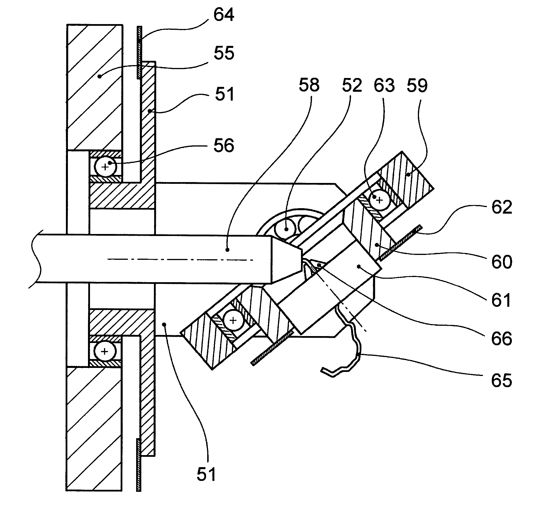
The present invention provides a reliable and efficient method for applying a permanent customized shape to an orthodontic archwire using robotic devices. The invention solves the problem of limited precision in the application of bends and twists to the wire, and provides a stiff design that allows for a combination of bends and twists at one location. The device includes a guide bushing for guiding the wire and a gripper for clamping the wire. The gripper is mounted on three bearings, and the rotational angles of the three axes will precisely document the passive or relaxed shape of the wire. The device can be calibrated and has low friction to minimize errors in the wire shape.

Problems solved by technology

While this implementation has specific advantages, it has the big disadvantage of consuming significant wire length.
For lingual archwires, this is far too much.

Method used


Image

  • Method and device for shaping an orthodontic archwire
  • Method and device for shaping an orthodontic archwire
  • Method and device for shaping an orthodontic archwire

Examples


Embodiment Construction

Six Axis Robot Having One Gripper

[0036] The robot as disclosed in U.S. Pat. No. 6,612,143 comprises two grippers, one of the grippers being mounted to a six-axis-robot arm and thus moveable in all six degrees of freedom. The other gripper is fixed to the base plate of the robot. The gripping tools preferably incorporate force sensors which are used to determine overbends needed to get the desired final shape of the archwire. The manufacturing process uses straight pieces of wire and step by step applies bends and / or twists to the wire, thus forming an archwire. The process as described in the '143 patent requires the calculation of the consumed wire length for a bend. In column 16 line 64 ff. it is described how such a calculation can be performed. Also, FIG. 20B displays a proposed algorithm. From the specification it becomes obvious that the exact calculation of the required straight wire length is not possible. Even a slight miscalculation of the consumed wire length for a bend...


PUM

PropertyMeasurementUnit
lengthaaaaaaaaaa
widthaaaaaaaaaa
lengthaaaaaaaaaa

Abstract

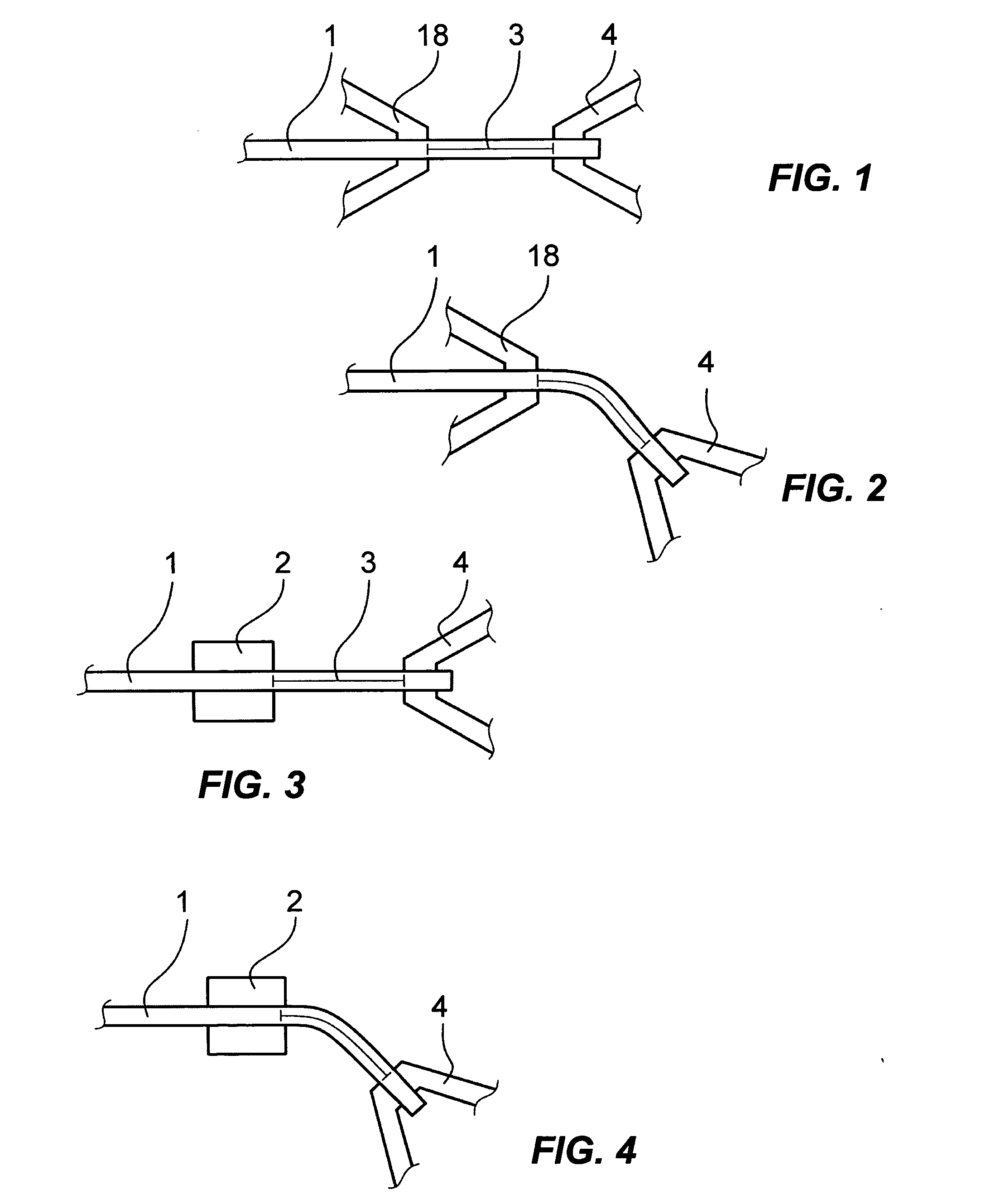
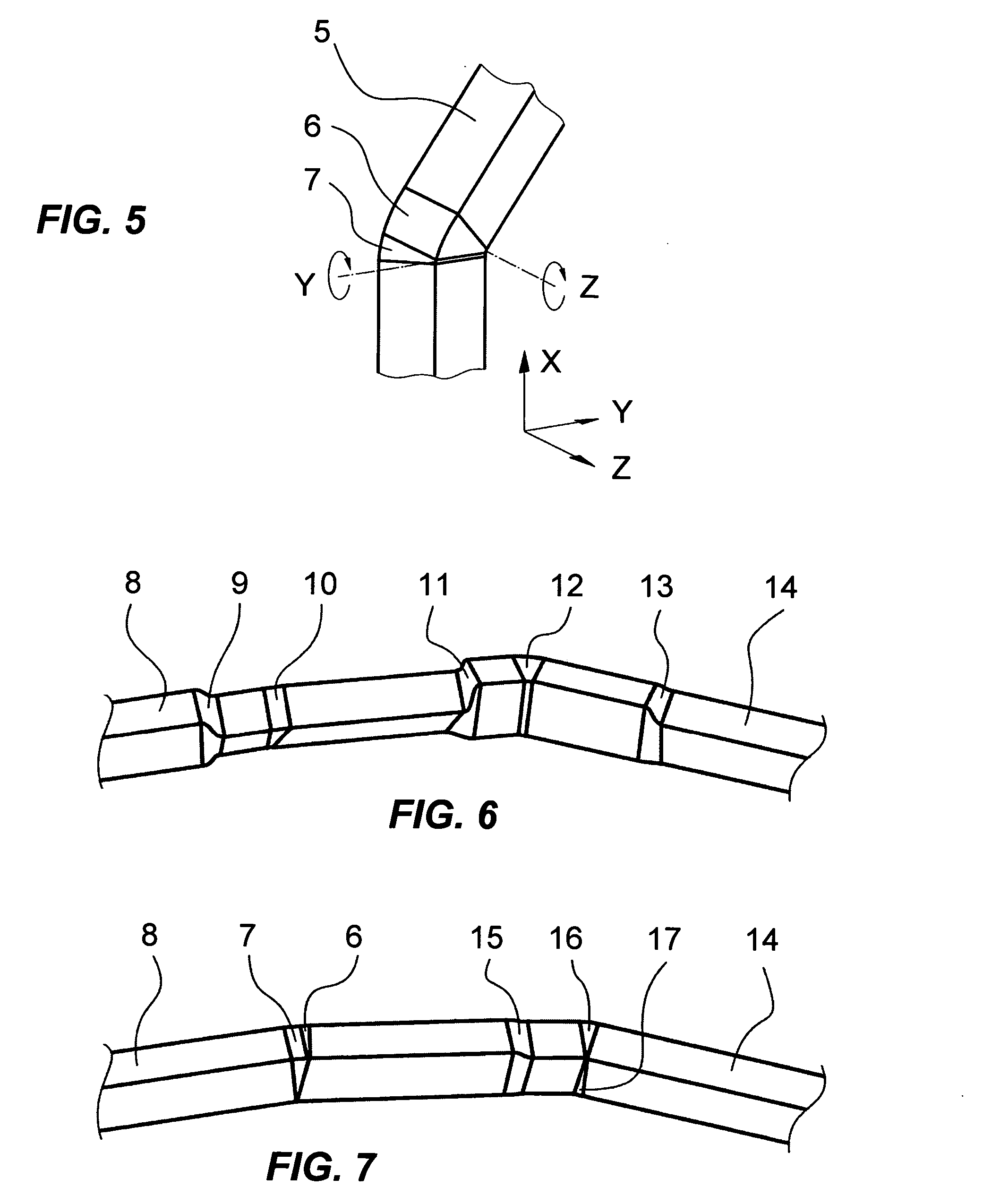
An apparatus for bending orthodontic wires has means for guiding and holding a wire. In order to prevent forces resulting from compressive or stretching strain during the bending process, one of these means does not apply any longitudinal forces onto the wire by design. In another implementation, the apparatus for bending orthodontic wires has a gimbal-mounted gripper for bending the wire. Furthermore, a method is disclosed for applying two bends at the same longitudinal wire location in two different directions.

Description

CROSS-REFERENCE TO RELATED APPLICATIONS [0001] Not applicable STATEMENT REGARDING FEDERALLY SPONSORED RESEARCH OR DEVELOPMENT [0002] Not applicable REFERENCE TO SEQUENCE LISTING, A TABLE, OR A COMPUTER PROGRAM LISTING COMPACT DISK APPENDIX [0003] Not applicable BACKGROUND OF THE INVENTION [0004] The present invention relates to methods for applying a desired shape to archwires to be used in orthodontic appliances for the straightening of teeth, and more particularly, to the automated manufacture of customized archwires using robotic devices. [0005] The common approach for orthodontic appliances is to bond small metallic parts (“brackets”) onto the outer (“labial”) side of the teeth, and to insert a wire into the slots of the brackets. The wires are typically preformed off-the-shelf wires, and the brackets are bonded basing on visual judgment by the orthodontist. However, the use of computerized processes in orthodontics increases. Especially when the brackets are bonded to the back ...

Claims


Application Information

Patent Timeline
Patent Type & Authority Applications(United States)
IPC IPC(8): B21D11/00
CPCA61C7/02A61C7/04B21F1/00B21F1/006B21F1/008B21F45/008
Inventor RUBBERT, RUEDGERWEISE, THOMAS
Owner 3M INNOVATIVE PROPERTIES CO
Learn More