
Apparatus for dry-surface cleaning using a laser

a technology of dry-surface cleaning and laser, which is applied in the direction of laser beam welding apparatus, chemistry apparatus and processes, manufacturing tools, etc., can solve the problems that materials sensitive to heat or light such as semiconductor devices, magnetic devices, organic materials, thin film coating layers, etc., and achieve the effect of preventing surface damag

Inactive Publication Date: 2006-05-25
IM TECH CO LTD
View PDF5 Cites 17 Cited by
  • Summary
  • Abstract
  • Description
  • Claims
  • Application Information

AI Technical Summary

Benefits of technology

[0009] It is, therefore, an object of the present invention to provide a dry-surface cleaning apparatus using a laser, which is capable of preventing a surface damage caused by directly irradiating a plasma thermal radiation onto a workpiece to be cleaned.

Problems solved by technology

However, none of dry-surface cleaning apparatuses is provided with a measurement capable of blocking the irradiation of the plasma thermal radiation.
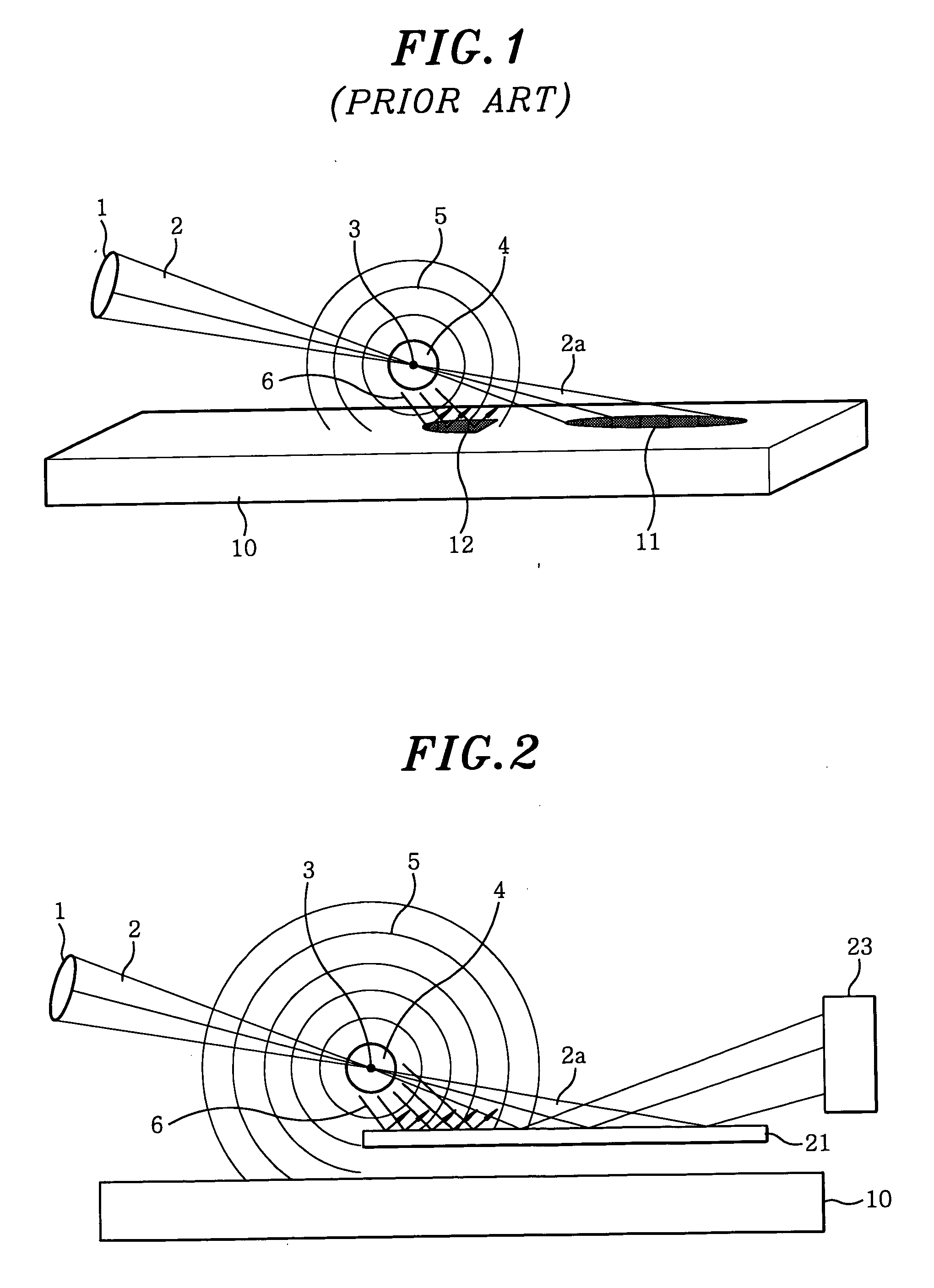
Especially, materials sensitive to heat or light such as semiconductor devices, magnetic devices, organic materials, thin film coating layers and the like may be seriously damaged on the surface thereof by the plasma thermal radiation 6.

Method used


Image

  • Apparatus for dry-surface cleaning using a laser
  • Apparatus for dry-surface cleaning using a laser
  • Apparatus for dry-surface cleaning using a laser

Examples


Embodiment Construction

[0016] Hereinafter, preferred embodiments of the dry-surface cleaning apparatus in accordance with the present invention will be described in detail with reference to the accompanying drawings, in which like reference numerals indicates like elements.

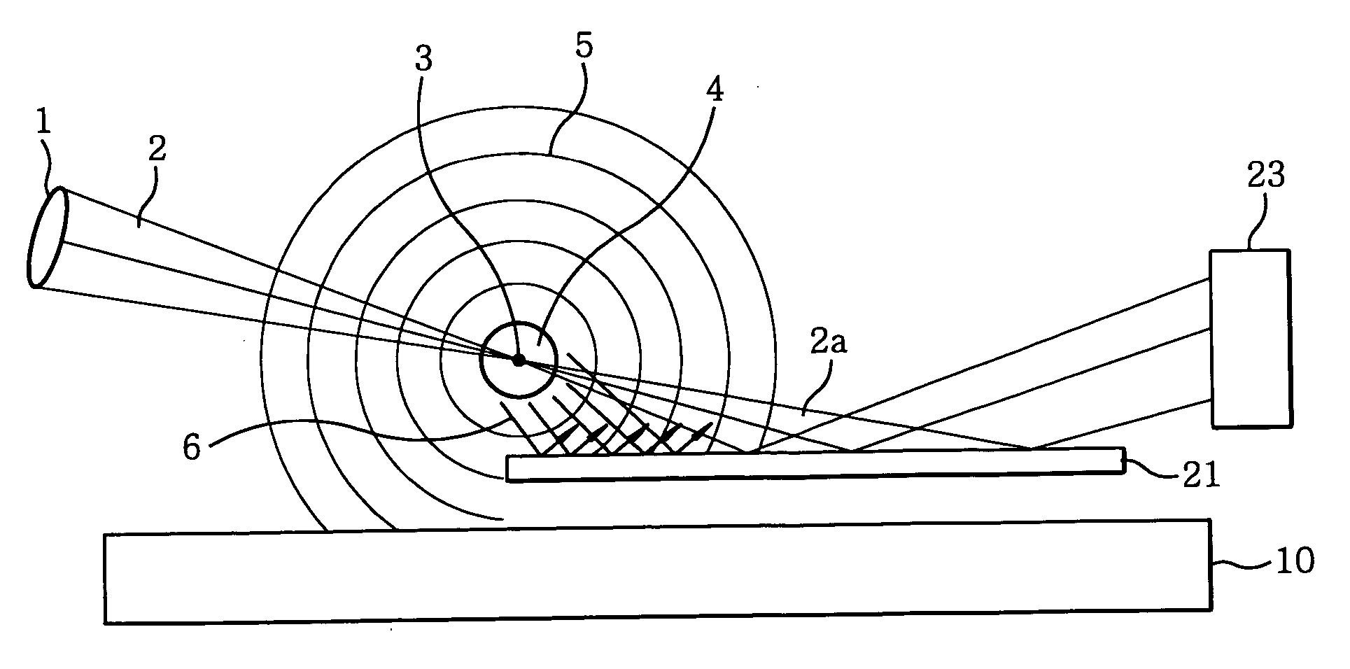
[0017]FIG. 2 describes a schematic view of a dry-surface cleaning apparatus using a laser in accordance with the present invention.

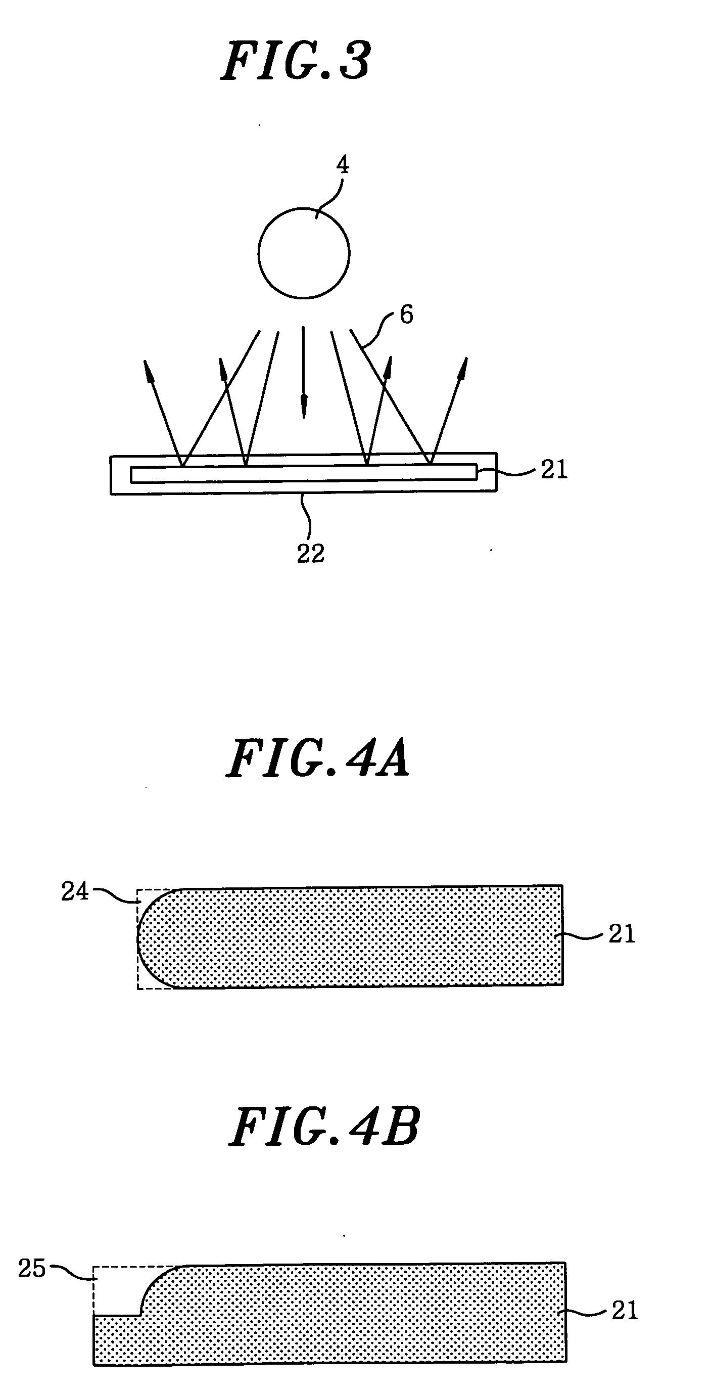
[0018] The dry-surface cleaning apparatus of the present invention includes a focus lens 1, a thermal radiation protector 21 and a laser beam absorber 23.

[0019] The focus lens 1 is used for converging the laser beam 2 produced from a laser (not shown) into a laser focus 3 in an air around a surface of a workpiece 10 to be cleaned. If energy of the laser beams 2 is greater than or equal to a threshold around the laser focus 3, the air itself around the laser focus 3 becomes ionized, thereby generating powerful plasma 4. Accordingly, a plasma shock wave 5 corresponding to the plasma 4 propagates to the work...


PUM

PropertyMeasurementUnit
shapeaaaaaaaaaa
transparentaaaaaaaaaa
energyaaaaaaaaaa

Abstract

A dry-surface cleaning apparatus includes a laser for generating laser beams, a focus lens for generating a plasma shock wave around a laser focus by converging the laser beams into the laser focus around a workpiece to be cleaned, wherein contaminants on the workpiece are removed by colliding the plasma shock wave against the workpiece, and a thermal radiation protector for avoiding a surface damage on the workpiece induced by a plasma thermal radiation entailed by the generation of the plasma shock wave. The thermal radiation protector is installed between the laser focus and the workpiece and is extended toward a downstream of the laser focus to a position where a portion of remaining laser beam when generating the plasma shock wave reaches in order to reflect the remaining laser beam.

Description

FIELD OF THE INVENTION [0001] The present invention relates to a dry-surface cleaning apparatus for removing contaminants on a workpiece using a laser; and, more particularly, to a dry-surface cleaning apparatus capable of blocking a surface damage on a workpiece from a plasma thermal radiation entailed by a laser induced shock wave. BACKGROUND OF THE INVENTION [0002] U.S. Pat. No. 5,023,424, entitled “Shock wave particle removal method and apparatus” discloses a technique for removing contaminants on a workpiece to be cleaned by generating a plasma shock wave using a laser and then colliding the generated plasma shock wave against the workpiece to be cleaned, wherein the plasma shock wave propagates from a laser focus in all directions by concentrating in the air a high-energy laser beam (0.1˜10 J / pulse) of a short pulse wave (below 1˜100 nanosecond) irradiated from a laser, which is incorporated herein by reference. [0003] Further, U.S. Pat. No. 6,635,845, entitled “Dry-surface cl...

Claims


Application Information

Patent Timeline
Patent Type & Authority Applications(United States)
IPC IPC(8): B23K26/00H01L21/304B08B7/00C21D10/00
CPCB08B7/0042C21D10/005H01L21/304
Inventor LEE, JONG-MYOUNGKIM, TAEHOON
Owner IM TECH CO LTD
Learn More