Dispensing container with flow control system

a flow control and container technology, applied in the field of container flow control system, can solve the problems of affecting the accuracy of dispensed liquid, affecting the quality of dispensed liquid, so as to avoid mistakes, improve accuracy, and make simple and inexpensive effects

a flow control and container technology, applied in the field of container flow control system, can solve the problems of affecting the accuracy of dispensed liquid, affecting the quality of dispensed liquid, so as to avoid mistakes, improve accuracy, and make simple and inexpensive effects

US20060108384A1Active Publication Date: 2006-05-25HOLOPACK INT CORP

Image

  • Dispensing container with flow control system
  • Dispensing container with flow control system
  • Dispensing container with flow control system

Examples


example 1

[0109] This example illustrates the calculation of the dimensions of the flow control system of the present invention.

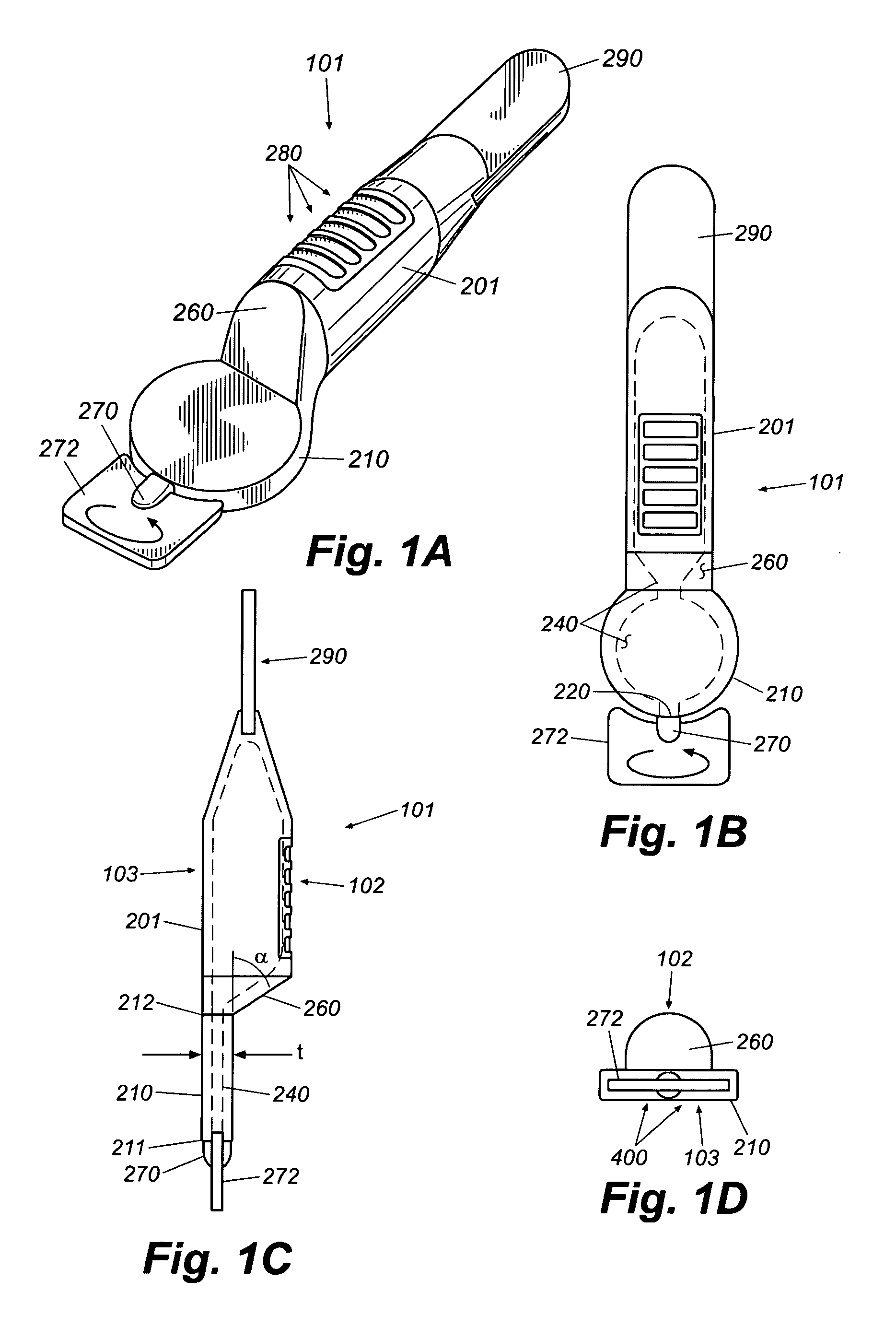
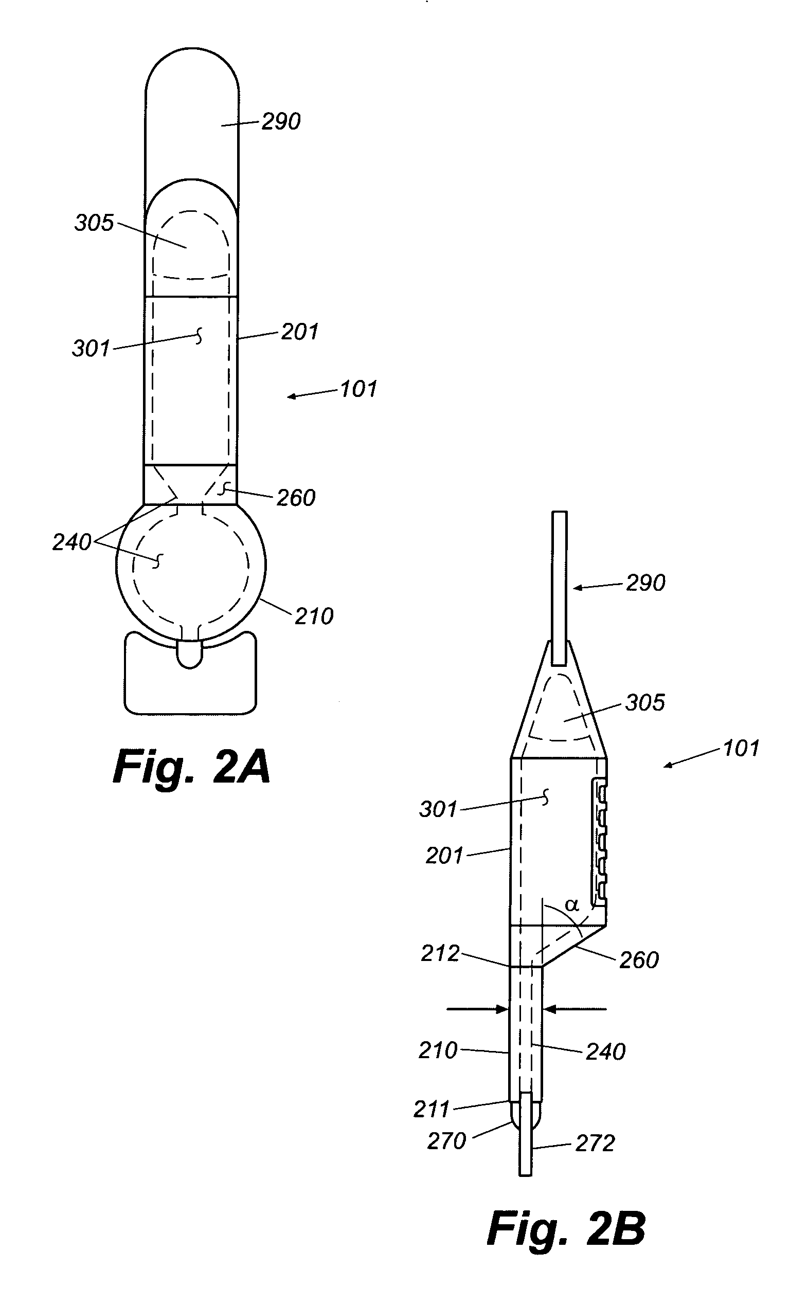
[0110] To illustrate how the outlet velocity can be influenced by the physical structure of the invention, a representative case is presented. The case involves a dual channel passage [240] as shown, for example, in FIGS. 10A-10D. For this case, the physical structure is constructed with channel lengths [240] L=33 mm+33 mm=66 mm total cumulative length, channel diameter, Dch=3.3 mm and Dout=1.9 mm. Fluid properties close to water are used in the model; namely, absolute viscosity, μ=1 centipoise at 20° C. and density, ρ=1000 kg / m3 at 20° C. For this physical structure, a 10 lbf squeeze creates a 57-mm-of-water reservoir pressure (see FIG. 15), resulting in a Reynolds number, Re=4600 indicating turbulent flow and an average fluid velocity in the channel, vavg=1.2 m / sec, which leads to a vout=7.6 m / s. If the viscosity of the fluid increases to 1000 centipoise and densi...


PUM

PropertyMeasurementUnit
velocityaaaaaaaaaa
velocityaaaaaaaaaa
delivery timeaaaaaaaaaa

Abstract

A dispensing container fillable with a liquid includes a squeezable reservoir for holding the liquid prior to dispensing, a dispensing outlet for expending the liquid, and a flow control system for regulating the velocity of the liquid exiting the outlet when a squeezing pressure is applied to the liquid-holding reservoir.

Description

CROSS-REFERENCE TO RELATED APPLICATION [0001] This application is a non-provisional patent application of U.S. Provisional Patent Application No. 60 / 630,716, filed Nov. 24, 2004, and titled DISPENSING CONTAINER, which is incorporated by reference herein in its entirety.BACKGROUND OF THE INVENTION [0002] (1) Field of the Invention [0003] The present invention relates to a flow-control system for a container for dispensing a liquid, and more particularly to a flow-control system for dispensing a measured amount of a liquid at a controlled rate. [0004] (2) Description of the Related Art [0005] Various dispensers for dispensing a liquid are known in the art. For example, various containers may be employed for dispensing liquids such as soap, eye wash, shampoo, ear wash, mouthwash, and medicine. These containers generally employ a flexible plastic reservoir portion for holding the liquid that can be squeezed to apply pressure to the liquid contained therein for transporting the liquid to...

Claims


Application Information

Patent Timeline
25 May 2006
Publication
US20060108384A1
IPC
B65D47/10
CPC
A61J1/067; B65D1/095; B65D75/5811
Inventors
ZAHN, WALTER; MILLER, SHAWN W.