Method and system to control movable entities

a technology of moving entities and control methods, applied in the field of control of moving entities, can solve the problems that the current system is limited to relaying gps information, and achieve the effect of decreasing increasing the speed of the entity

Active Publication Date: 2006-05-25
WIRELESSWERX IP LLC
View PDF25 Cites 66 Cited by
  • Summary
  • Abstract
  • Description
  • Claims
  • Application Information

AI Technical Summary

Benefits of technology

[0011] In another aspect, the configurable operation can be turning on an ignition to the entity, turning off the ignition to the entity, increasing speed of the entity, decreasing speed of the entity, regulating the engine temperature level, regulating the internal temperature level, locking a door or latch of the entity, unlocking of a door or latch of the entity, opening a window of the entity, closing of a window of the entity, turning on a light indicator, change tire air pressure, turning on an alarm, or turning off an alarm.
[0018] In one aspect, the configurable operation is turning on an ignition to the entity, turning off the ignition to the entity, increasing speed of the entity, decreasing speed of the entity, regulating the engine temperature level, regulating the internal temperature level, locking a door or latch of the entity, unlocking of a door or latch of the entity, opening a window of the entity, closing of a window of the entity, turning on a light indicator, changing a tire air pressure, turning on an alarm, or turning off an alarm.

Problems solved by technology

Current systems are limited to relaying the GPS information to a control center or a web server and plotting the position of the vehicle on a computer map.

Method used


Image

  • Method and system to control movable entities
  • Method and system to control movable entities
  • Method and system to control movable entities

Examples


Embodiment Construction

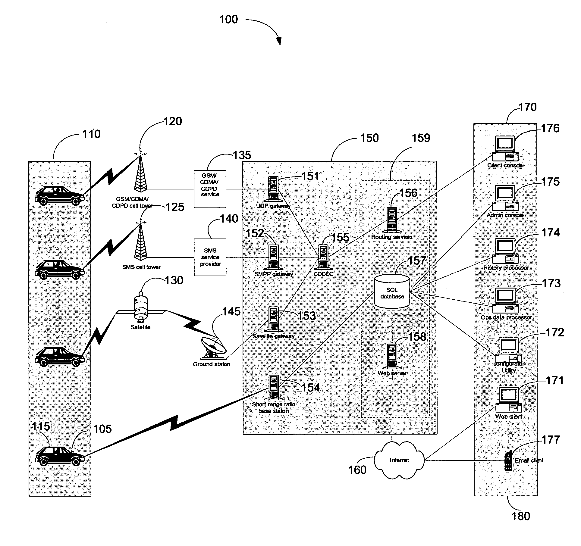
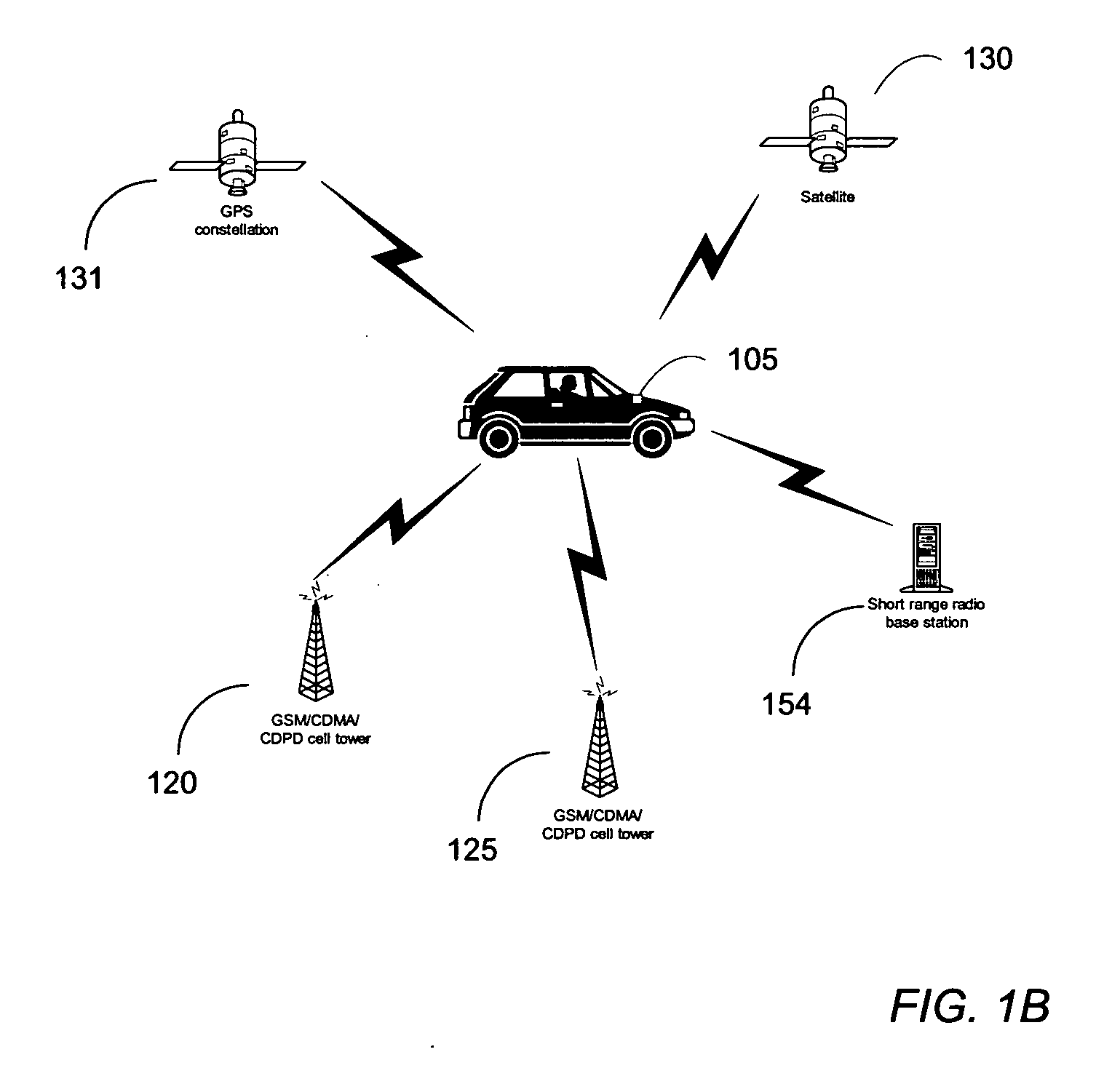
[0055] Asset management and monitoring devices that use ground positioning systems allow users to track the position of vehicles and cargo and other entities. The method and system described below utilizes a transponder that communicates over cellular and satellite communication networks in combination with GPS positioning satellites capable of providing position and status information on a global scale. The transponder allows interaction with and control of a wide range of peripheral devices, including operating according to preconfigured geographical zones and events.

[0056] A transponder can be mounted, attached, manufactured, or otherwise included upon / in various articles or entities. Such articles or entities may include vehicles, aircraft, cargo, persons, animals, or any other item where tracking its movement and / or location is beneficial. Within the context of the tracking system, the transponder works to collect, process, and communicate information about the article or enti...


PUM


Abstract

A method to wirelessly control an entity having an attached transponder is disclosed. A geographical zone is defined. The geographical zone can be defined by allowing a user to define and load to a transponder a plurality of waypoints, each waypoint defined by a geographical coordinate and a radius originating from the geographical coordinate. The geographical zone can also be defined by selecting a plurality of coordinates that are loaded to a transponder and mapped on a pixilated image. The microprocessor in the transponder is programmed to determine the occurrence of an event associated with the status of the entity in relation to the geographical zone. Finally, the microprocessor is configured to execute a configurable operation if the event occurs.

Description

CROSS-REFERENCE TO RELATED APPLICATIONS [0001] This application claims the benefit of the prior filing date of U.S. provisional patent application No. 60 / 625,467, filed Nov. 5, 2004, herein incorporated by reference in its entirety. This application is related to U.S. Utility Patent Application filed on Apr. 13, 2005, entitled “METHOD AND SYSTEM TO CONFIGURE AND UTILIZE GEOGRAPHICAL ZONES” (Docket No. 81221-010301, Express Mail Label No. EV 310 126 159 US); and U.S. Utility Patent Application filed on Apr. 13, 2005, entitled “METHOD AND SYSTEM TO MONITOR MOVABLE ENTITIES” (Docket No. 81221-010302, Express Mail Label No. EV 310 126 162 US); both of which have been filed concurrently and are incorporated by reference in its entirety.FIELD OF THE DISCLOSURE [0002] The disclosure relates to controlling movable entities. In particular, it relates to systems and methods to remotely control and monitor movable entities functions and positioning data in relation to pre-configured geographic...

Claims


Application Information

Patent Timeline
Patent Type & Authority Applications(United States)
IPC IPC(8): G08B1/08G08B23/00G08B5/22H04W4/021H04M1/72409H04M1/72412H04W4/029H04W4/40H04W4/80
CPCB60R25/00B60R25/04B60R25/1004B60R25/102B60R25/33B60R2325/101B60R2325/304G07C9/00111G08B25/14G08G1/20G08G1/207H04W4/021H04W4/046H04W4/80H04W4/40G07C9/28H04W4/029G01C21/26H04W84/12
Inventor STATON, HOUSTONASHLEY, JAMES SR.ASHLEY, JAMES JR.MOONEY, FRANKMOONEY, PATRICKLANG, EDWARDMAGGS, CHARLESSANTOS, GERMAN
Owner WIRELESSWERX IP LLC
Why Eureka
Try Eureka